What are the Mappings
The logic of the Mappings Map in place, SMIP is used in many places in the VSoft archITekt platform.
The Mappings are used in the User Interface when creating forms on the Initial mapping tab, and also as a map in place editor in the Data processing packages.
In the documentation, the terms for the Mappings may be used interchangeably as Map in place (SMIP), and such as Map in place editor (Mappings designer), etc.
Map in place (also known as SMIP = Schema Map in place) is a fragment of the logic used in many places in the Application. Mapping is defined by the list of operations to be performed. The operations available may be divided into the ones which change a schema only (and do not take up time while processing!) and the ones which change data records content. Operations to be performed are added by using the context menu and assigning an annotation to the field/record. See: Annotations.
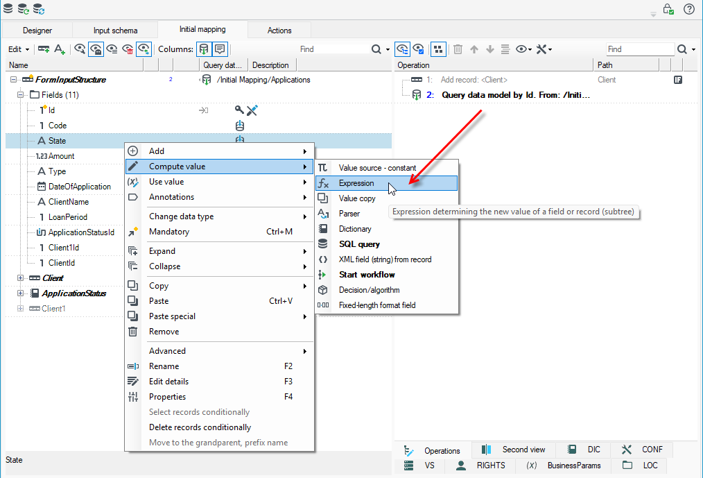
A Map in place (SMIP) element appears as a component of many transformation blocks, including:
- Map in place (all operation options available),
- Database writer (additionally, to insert database-specific annotations),
- Save to XML (as above, in order to insert mapping annotations to XML),
- Normalizer (in order to insert normalization rule).
As each record transformation, the SMIP logic consists of two elements:
- transformation of schemas - changes an input data schema into an output one, creating additional descriptions required for quicker transformation at the data transformation stage. It also validates defined operations (e.g. mandatory status of fields, validity of expressions, availability of references to dictionaries, etc.). This stage is performed many times during work in the designer and it is performed only once before running on data.
- transformation of records - done separately for each input record and for that reason it is highly optimized.
Mappings Designer
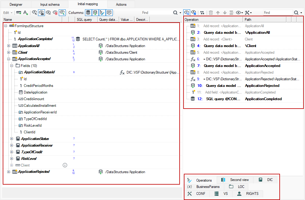
It consists of two panels:
Left - shows only a data schema. The data schema is organized in the form of a tree. For more see Data schema.
The set of tabs visible in the right panel varies depending on whether the mapping designer is open in the context of a form or processing packages.
Right – contains tabs:
- Operations - for more see: Operations
- Second view of data schema (useful when working with large schemas to avoid scrolling content ).
- ARG: contains the data tree of the package call arguments
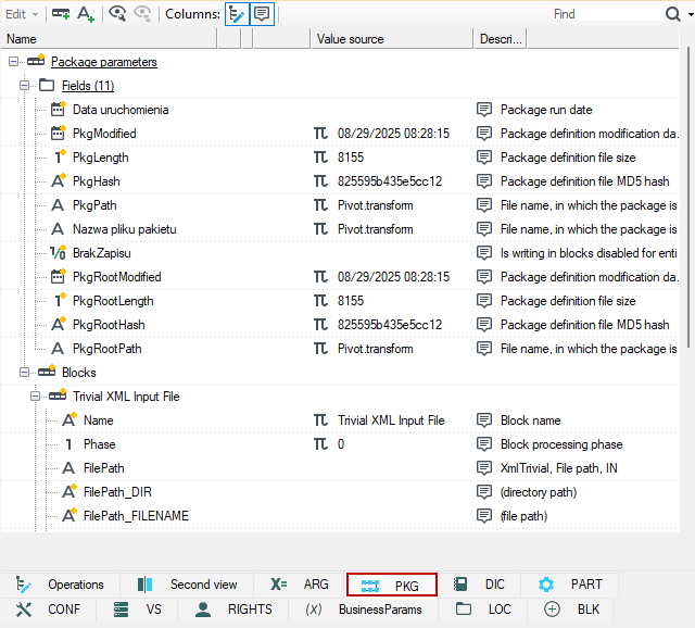
- PKG: contains parameter values of package elements (e.g., processing start time) and its components (e.g., details of individual blocks),
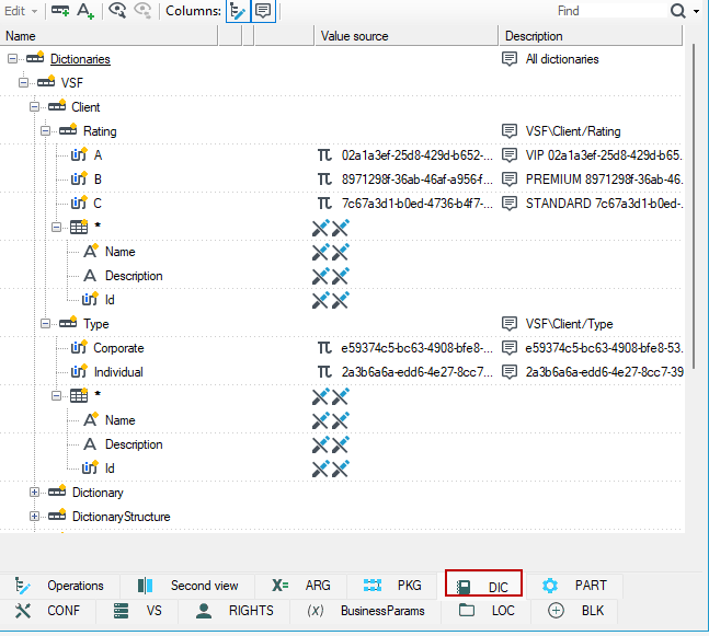
- DIC: lists available dictionaries with columns
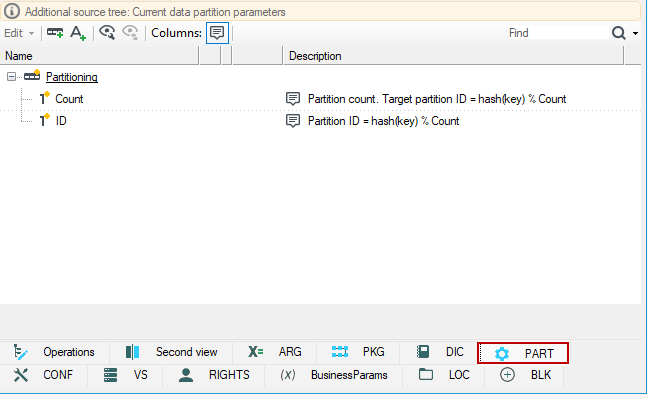
- PART: Current data partition parameters
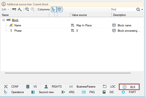
- BLK: current block data.
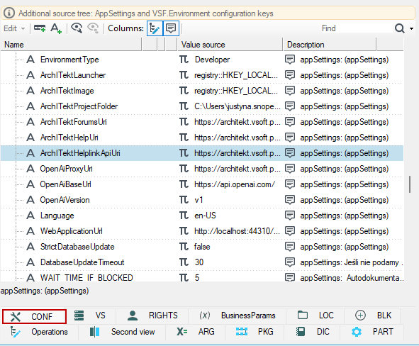
- CONF: Configuration keys accessible from the main configuration (appSettings), .ini file and other technical configuration sources. A comment for each item indicates the source of the key.
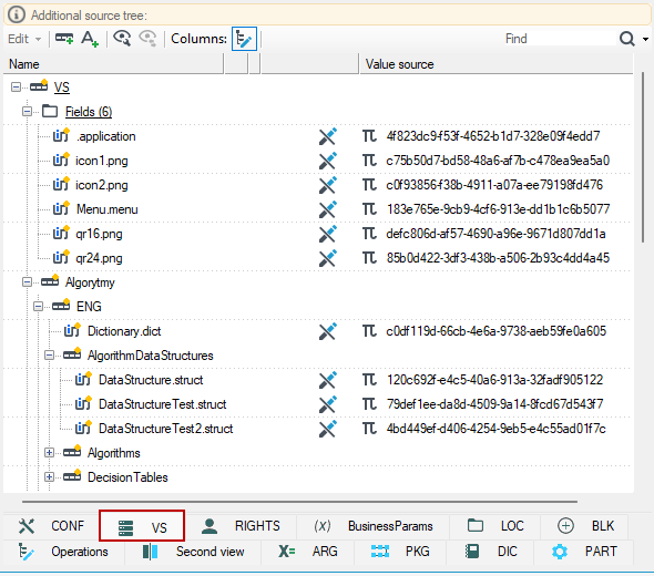
- VS: A tree with the contents of the version server along with the GUID of each version.
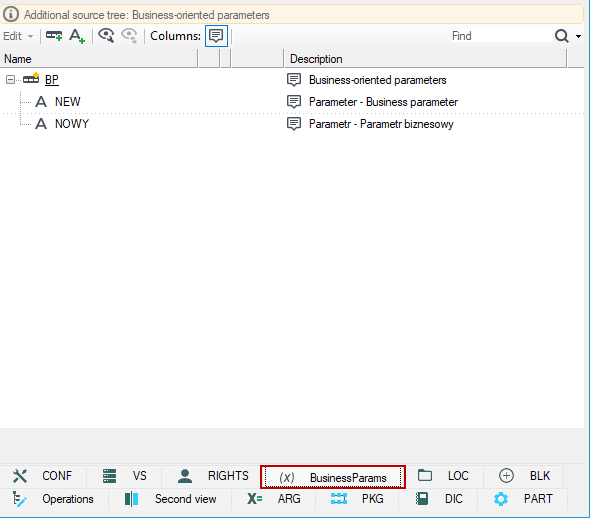
- BusinessParam: tree of business parameters if defined - about defining business parameters see Business parameters.
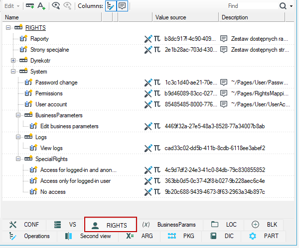
- RIGHTS: list of special pages defined in archITekt Studio and system pages.
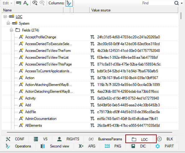
- LOC: list of local variables defined in arhITekt Studio.
ARG, PKG, BusinessParams, RIGHTS, DIC, PART, CONF, VS, LOC tabs represent named trees. Dragging named tree elements from these tabs onto data schema elements on the left panel of the editor adds an Expression annotation to the target element and sets the dragged element to the source of the expression value.