Transformation blocks
The chapter contains a detailed description of transformation blocks.
Blocks are placed on the right side of the window in the menu Toolbox.
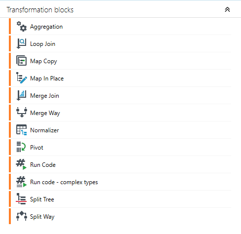
These include the following types of blocks:
- Map In Place
- Loop Join
- Normalizer
- Split Tree
- Split Way
- Merge Join
- Merge Way
- Aggregation
- Run Code
- Pivot
- Map Copy
- Run code - complex types
Map In Place

The Map In Place option enables processing and modifying a data record being mapped without creating a copy.
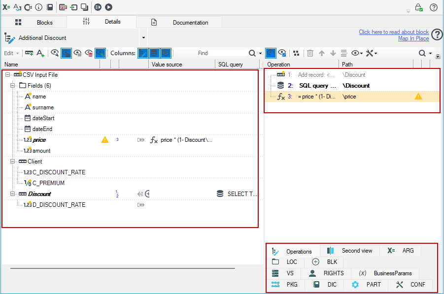
The tab Details enables performing any operations on records and data fields. Operations on particular data elements are described in details in the chapter devoted to adjusting record schemes and fields see: Data processing .
The tab Operations contains a chronological list of changes which occurred during data modification. A list of changes will be executed on each record which passes through a block. A window toolbar enables:

- displaying operations related to a node - Show operations connected to a node,
- selecting nodes related to an operation- Select nodes connected with operation,
- grouping operations -Group operations,
- deleting operations - Remove operations,
- moving operations up - Move selected operation up,
- moving operations down - Move selected operations down,
- inserting operations being executed in the selected place (as opposed to inserting them at the end, which is a default behavior) - Insert new operations at selection point,
- access to the context menu Operations and Tools.
When working with a large data schema (with a number of fields/records), the second view of the block details can be used - the tab Second view. Such solution enables modifying data at two levels at the same time which minimizes time required to make modifications and facilitates User's work. Both windows interact with each other and make moving elements in the tree easier.
Loop Join

The block Loop Join enables joining the query results from an additional source to records from the original source. The tab Details is used for determining the conditions of getting information from the attached sources.
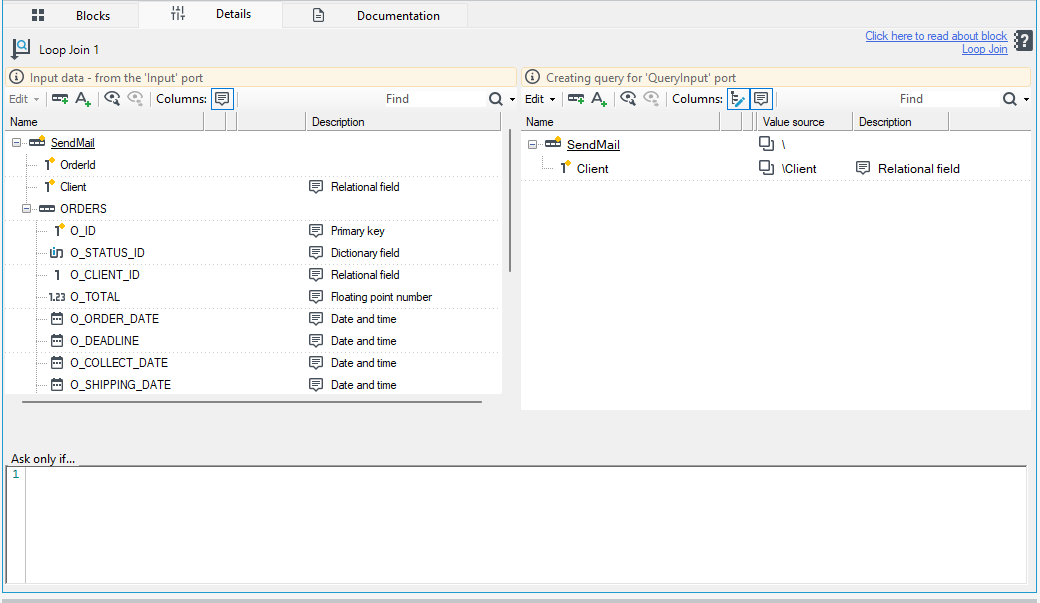
- The User defines the required queries to an additional source (a port which lets data through from additional source).
- A window Input data from the "Input" port shows the preview of the input data schema which comes from the first source. The next window enables making a query to a 'QueryInput' port - data from an additional source. Only data which meet requirements will be let through.
- A window Ask only if enables defining a condition for the operation executed by the block.
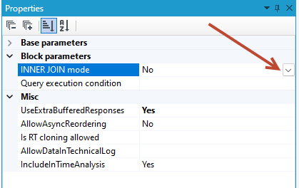
Additionally, setting the field 'InnerJoin' which is available in the block's properties (the tab Properties) indicates that the next records should be skipped from processing if query returns no data.
Example:
When building a package that retrieves customer data from the CLIENT table and the corresponding applications from the APPLICATIONS table, the first data-read block fetches the customer data from the database.
In the Loop Join block, the field C_ID is moved to the right side — this is the field used to join the data coming from the second source, i.e., the list of applications.
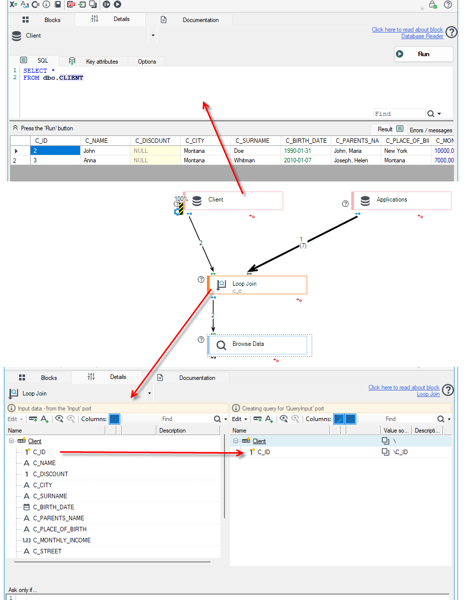
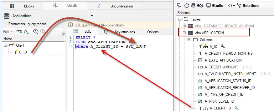
In the next database read block - Applications, you need to specify that only applications assigned to the given client ID C_ID should be retrieved. To do this, use the relational field A_CLIENT_ID in the query, which should match the client ID.
An example of the query syntax is shown below.
Normalizer

The block Normalizer enables changing a data structure from a redundant table to a branching tree.
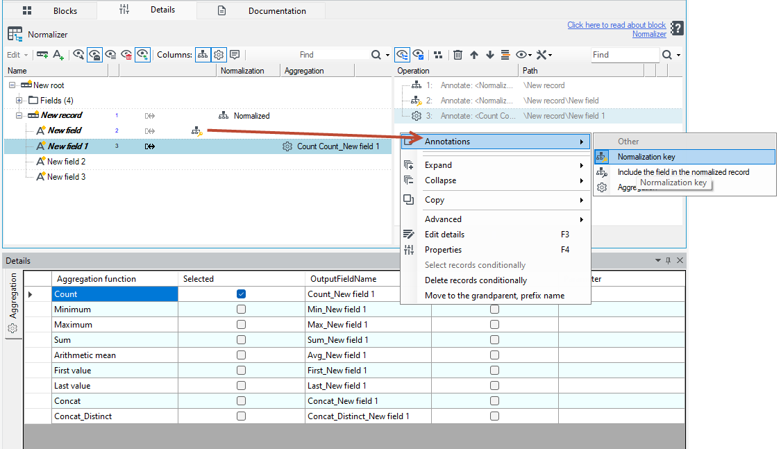
- The block Normalizer is used for changing flat records which source is a data base or a CSV input file to trees in the form Parent – multiple children.
- Select the record/field and choose the appropriate annotation from the context menu.
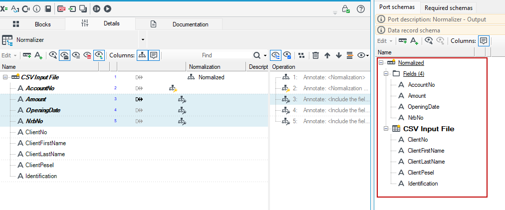
- Activate the Schemas panel to see which field has been normalised.
An example of this block execution is a process when records in the following form have been obtained from a flat file:

As shown in the figure, a record contains "flattened" data of an account and one client. A proper relation to be obtained is an account which has clients as records-children:

The next records retrieved from a data source contain the same data in the fields which concern an account and data of the next client in the other fields. Each parent record is identified by a unique key (AccountNo in this case) which indicates if client's data concerns a current account.
The result described above may be obtained by marking elements with proper annotations which are available only for the block Normalizer.
Elements may be marked with annotations in one of the following ways:
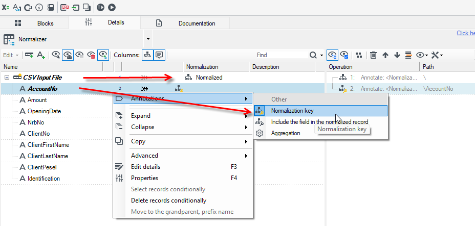
1st method:
- a record to be "normalized" should be marked with an annotation Normalization,
- a key which uniquely identifies which parent record should be marked with an annotation Normalization key (in the above-mentioned example, the element AccountNo should be marked with this annotation).
2nd method:
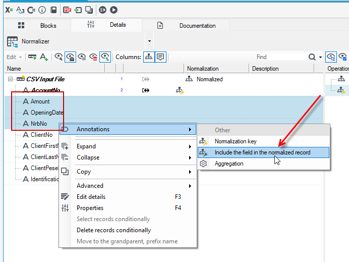
- all fields belonging to a parent record (repeating for all flat records with the same key) should be marked with an annotation Include in normalized record (as far as the above example is concerned, the elements: Amount, OpeningDate and AccountNo should be marked with this annotation),
- a record to be "normalized" should be marked with an annotation Normalization. All the options related to record normalization for this annotation are set in the Details editor.
The data schema is as follows:
Normalization and Sorting of Data
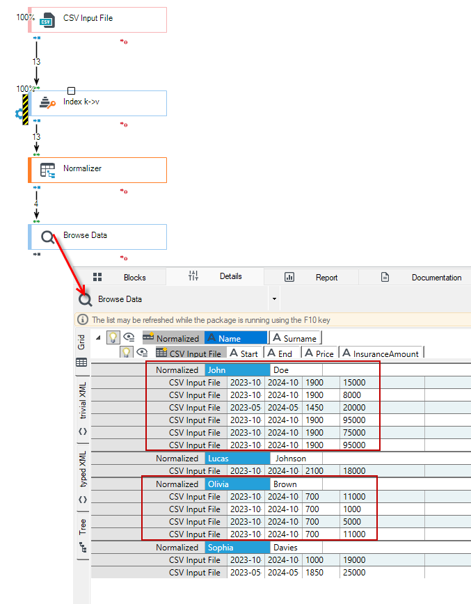
The simplest processing package can be built from the following blocks:
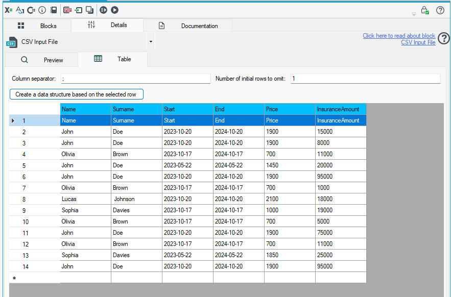
- CSV Input File – This block loads customer data. It is a flat structure where customer records are repeated.
- Normalizer – This block allows changing the data structure, resulting in a tree-like structure, where a customer record is paired with their insurance data.
- In this block, specify the fields by which the data will be normalized. For the fields Name and Surname add the annotation Normalization key.
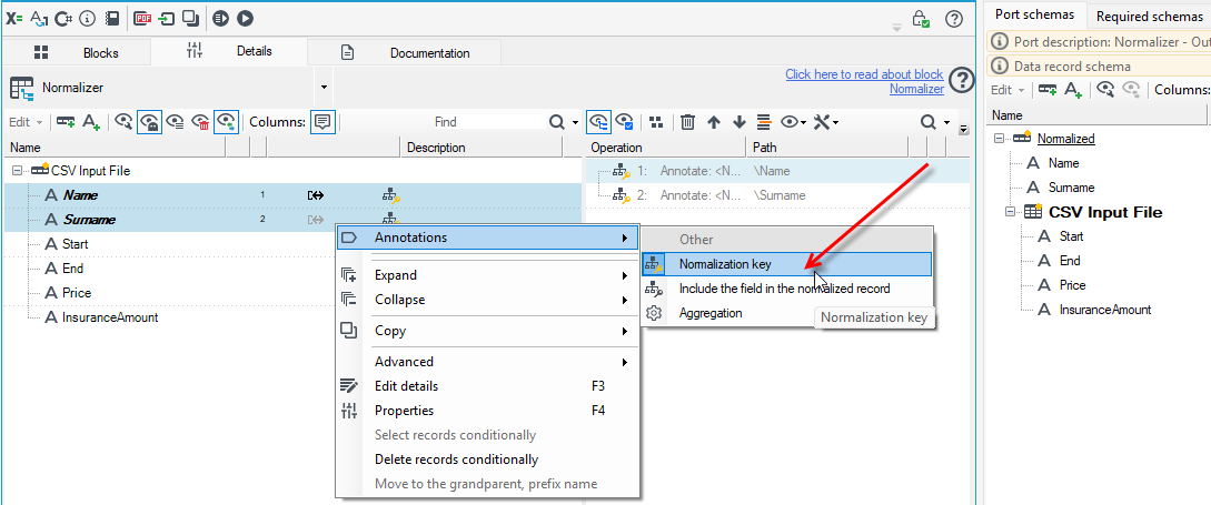
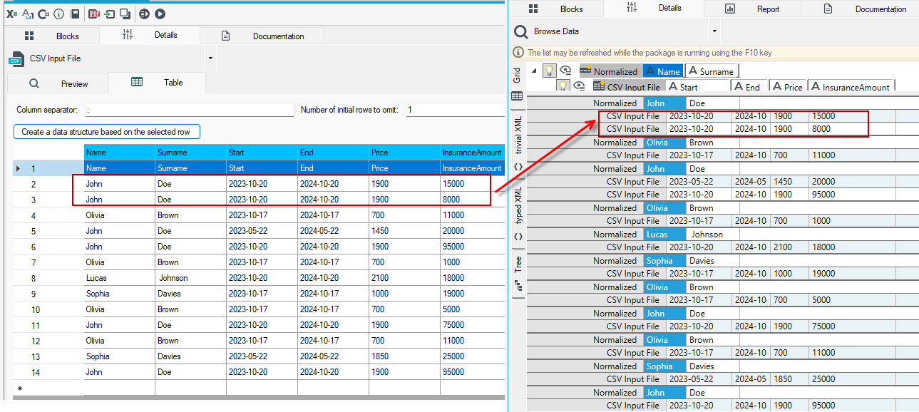
- Browse Data block – After adding this block, you can run the package and observe how the data has been transformed. In the example below, it can be seen that records appearing consecutively in the input file are normalized.
- If all data is to be normalized, the records should be sorted first.
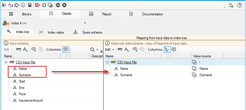
- Add the Index k>v block. In the block details, determine how the data should be sorted. Here, it should be by Name and Surname. Drag the fields to the right side.
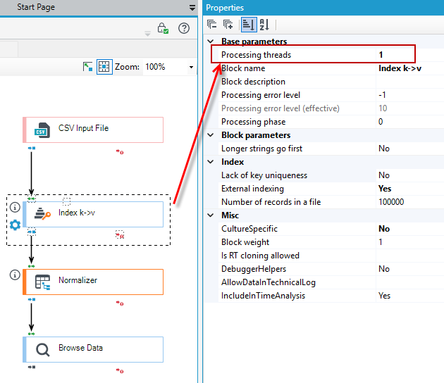
- The block also requires setting the processing thread. This means specifying that the block will be run first, gathering all the data preceding it, and then processing it.
- With this modified package, you will obtain normalized and sorted data.
The values of the normalization control field-keys are compared between neighboring records, and you should take care of their proper alignment yourself before using the normalize, e.g. sorting in the source or using the Index k->v block, or sorting operations (within a single record). In the latter case, if the normalization is performed inside a record ( and not between records), it is possible to group source records (incomplete sorting) before normalization within the normalization block itself - to do this, enable the Group items before normalization option on the Properties panel.
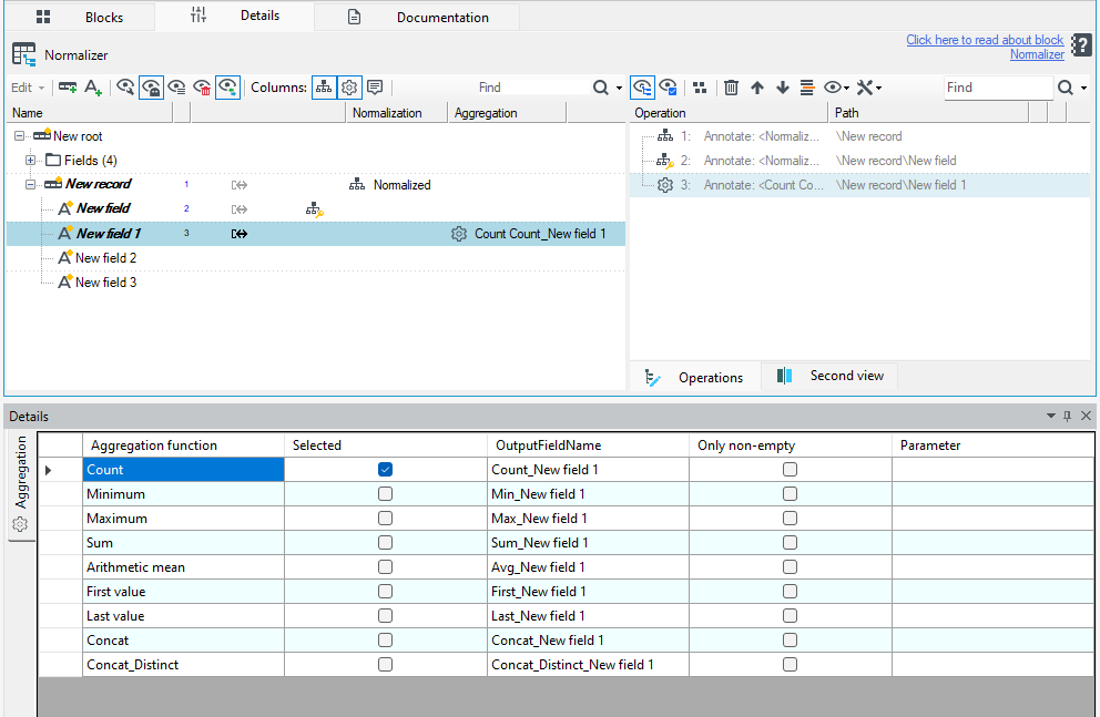
The fields to be normalized can additionally be aggregated on a similar basis as in the Aggregation block. When fields are marked with the Aggregation annotation, fields with names that are a concatenation of the aggregation name and the source field will appear in the resulting structure.
Split Tree

The block Split Tree enables splitting records into parts, conditionally "cutting off" or cloning subtrees in the indicated place.This block has 3 outputs (it is not mandatory to use all of them).
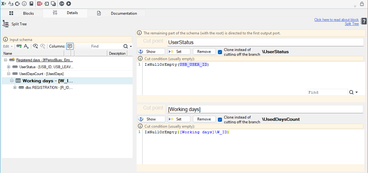
- In the block details, the User may define where records should be split.
- Select the proper data record and then press the Set button. Input file records will be split into two parts. All elements below the selected record will be directed to the second block output.
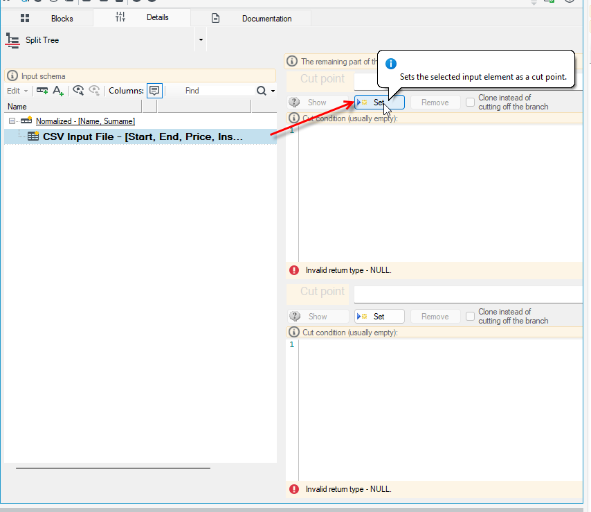
- The Show button shows in the tree (in the left panel) where records will be split.
- The Delete button deletes the defined split.
- The option Clone instead of cutting off the branch does not cut off the branch but copies it and sends it through the second output. All elements below the selected record will be directed to the second block output as a copy. Data from the entire tree will flow through the first output.
- In the middle window, the User may enter a condition for the action of splitting records. The system also has the function of predicting syntax in the language used for describing conditions (see: Programming language).
An example of using the block could be the continuation of the processing package describing the use of the Normalizer block (see: Normalizer).
- After loading the data from the CSV file and using the Normalizer block, add the Split Tree block.
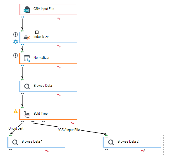
- Specify the cutting point on the data schema.
- The uncropped part of the schema will exit the block as the first output, which are the account data. The second output will direct the records starting from the cutting point, i.e., the customer data.
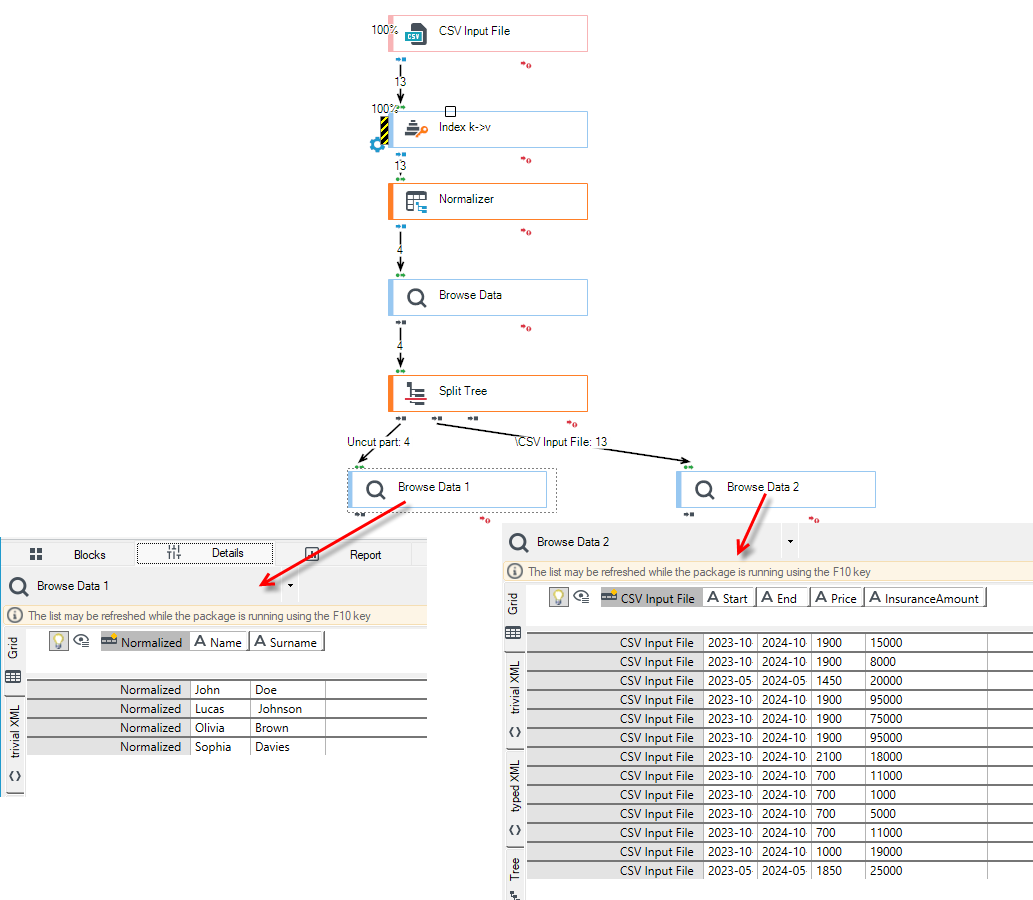
Split Way

The System enables proper classification and segregation of file records using expressions assigned to particular ports, using the Split Way block.
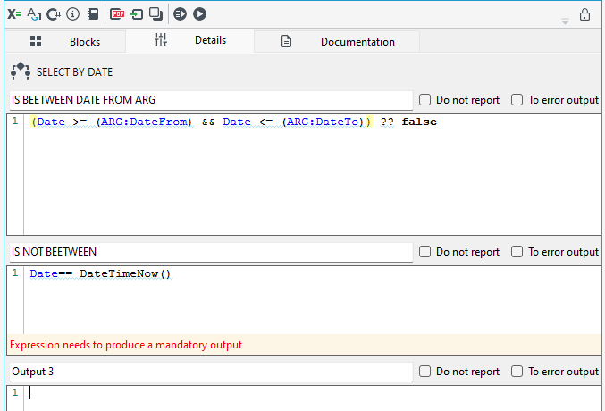
- Classification of records is done by conditioning the assignment of specific query results to particular ports.
- A block details window has been divided into three areas which have been assigned to three output blocks. Using specified expressions, the User defines which data should be sent using the specified output (see: Programming language ).
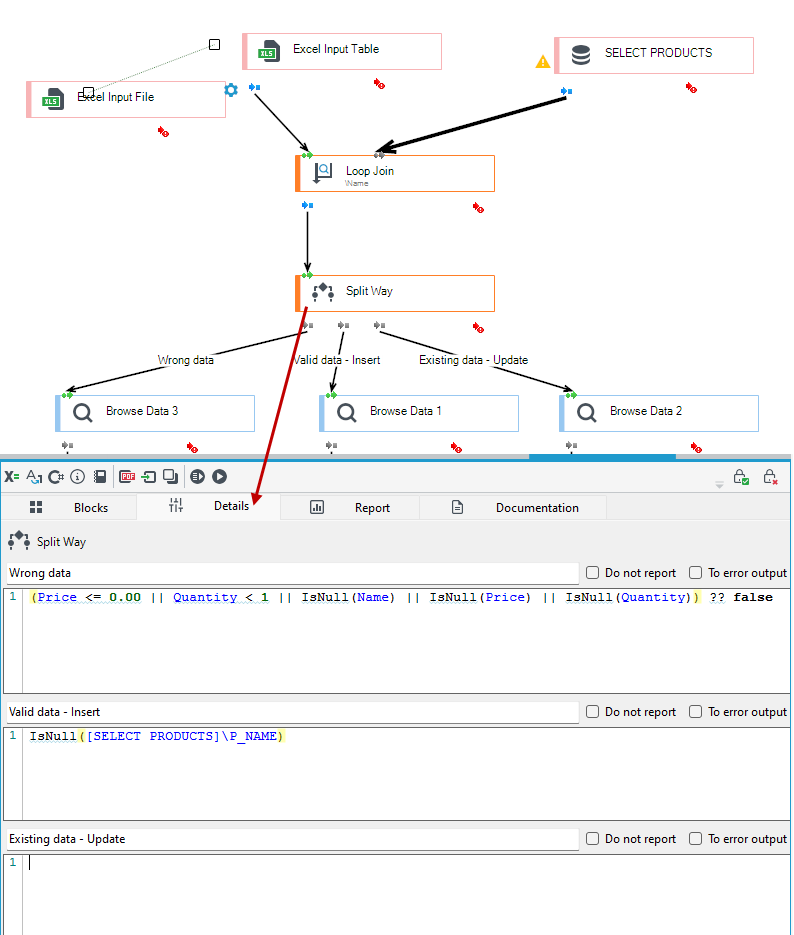
- Additional functionality of the block is reporting (i.a. to a log file) the number of records which have been entered by the specified output. The User may disable computing record statistics for the given port by selecting the option Do not report. If you want to disable reporting for the entire block you should select the option Disable reporting in the block properties.
Moreover, the field OperationMode in the block properties (the tab Properties) enables defining classification rules:
FIRST_ONLY- records being processed are classified by the first rule they encounter;MANY- records being processed are classified by all rules.
Example:
A record being processed: client's data.
Rules:
- Output 1: Sex: male.
- Output 2: Driving licence: yes.
- Output 3: Position: Computer scientist.
Client's data: sex: woman, driving licence: yes, position: computer scientist.
If the option First_ONLY is selected, records will go to output 2.
If the option MANY is selected, records will go to output 2 and output 3.
For an example of using the block, see: Writing records to the database with certain conditions.
Merge Join

The block Merge Join enables joining records which come from two record streams in one set of sorted records.
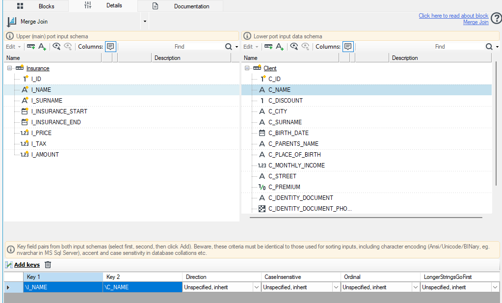
The window of the tab Details has been divided into two views which show the preview of two record sets coming from data streams.
- In order to determine the keys which define joining, appropriate tree elements of each view should be selected and the button Add keys should be pressed. The defined key preview will be displayed in the bottom window.
- Next, records are compared by the System using selected keys. If the keys are equal, records are joined. If joining a record with a record of the second output fails, it goes to the second block output (an output with records not joined).
If elements coming from outputs are found to be unsorted, the package processing is stopped.
A block may join records which come from both outputs in one of the following ways:
- Child-parent relation between input records - a record from the second input is attached as a "child" to a record from the first input.
- Records on the output as sibling with a new root - a new, artificial record-root is created and records of both inputs are attached to it as its children.
A connected subgraph in which such option of record joining occurs must have exactly one processing thread enabled.
- Record schemes overlay - output records issued one at a time - one record is fetched from each input, an output record with an algebraically smaller key is directed to the output, additionally, an output record has a new schema which is a common part of both outputs schemes.
- Record schemes overlay - an output record issued as a package - records are fetched from both inputs, all records with the same key are joined to be a list and directed to the output with a new record-root.
For example:
We retrieve data from two different tables: INSURANCE and CLIENT
- Records in both tables in the database must be sorted in the same way.
- Go to the block details and modify the query accordingly. In the example below, the records were sorted by the fields
C_NAMEandC_SURNAMEin theCLIENTtable, and byI_NAMEandI_SURNAMEin theINSURANCEtable.
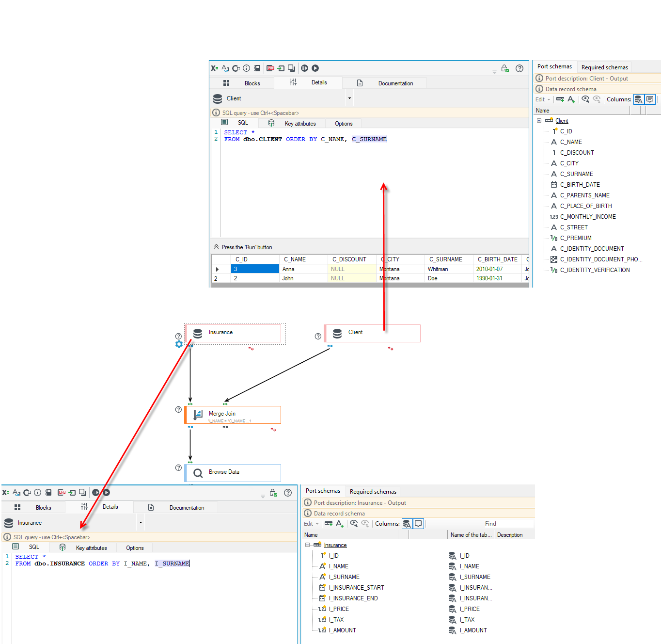
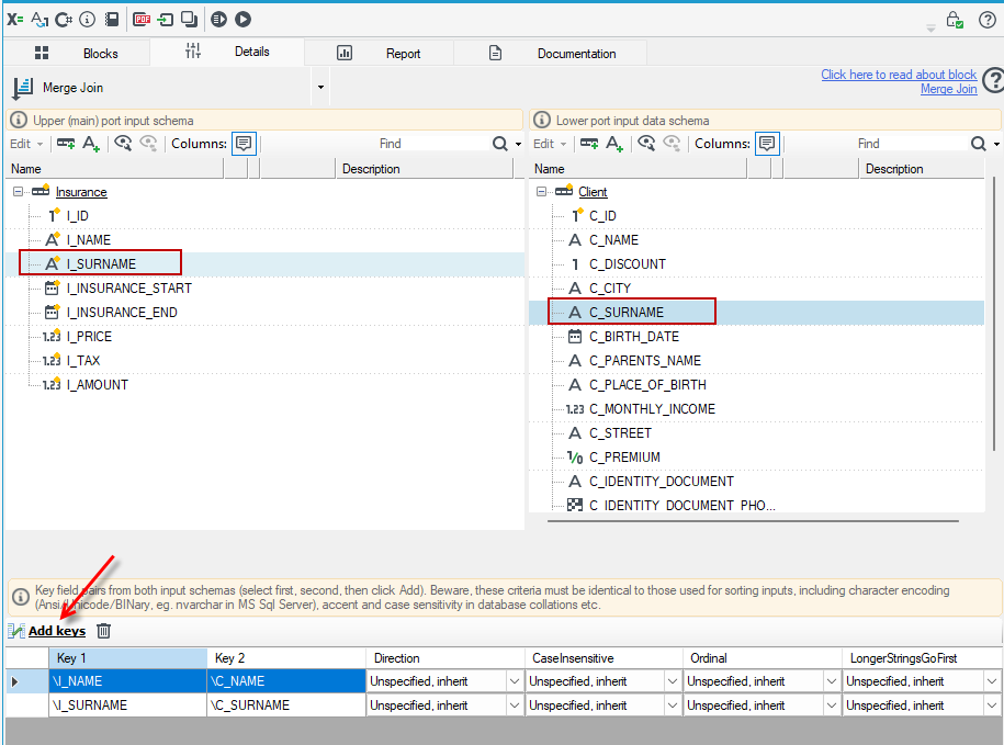
- Add the Merge Join block and go to the details. In the block, you need to specify the corresponding keys.
- Select the
I_NAMEfield on the left and theC_NAMEfield on the right, then click the Add keys button. - Do the same for the
I_SURNAMEandC_SURNAMEfields.
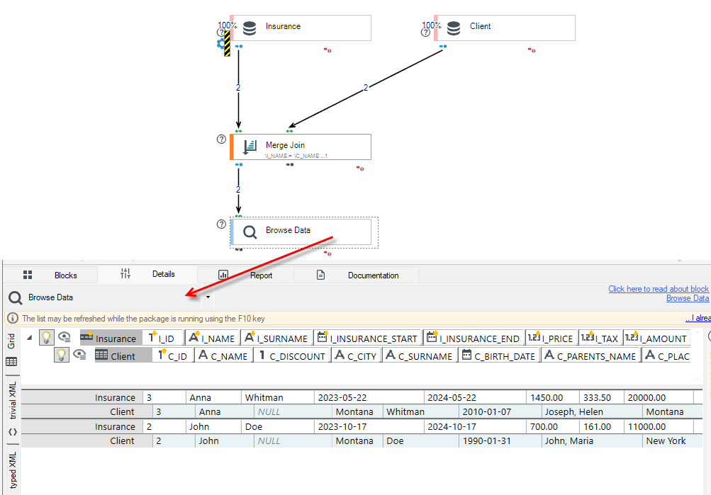
Now, you can run the package and, in the Browse Data block, see how the records were merged and sorted.
Merge Way

The Merge Way block enables merging the processing paths which have been split earlier during classification.
The block does not have to be configured in details. Paths are joined automatically. The figure below shows a processing package where the discussed function has been used.
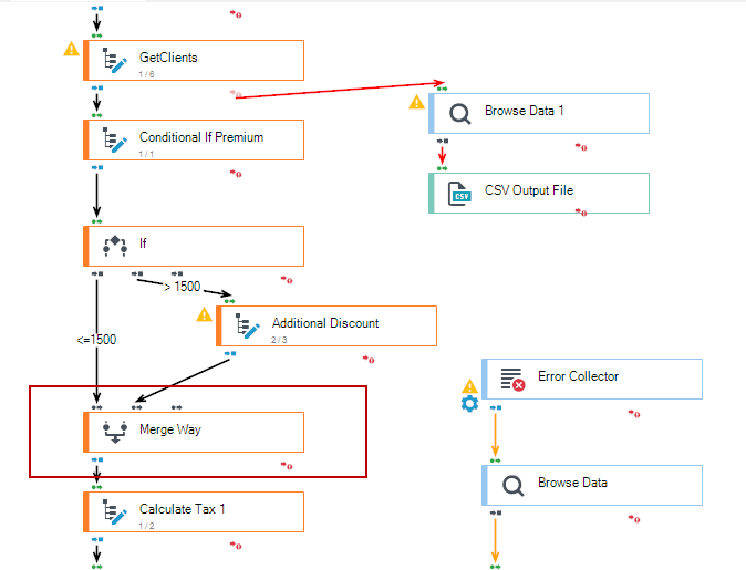
This block is often added after using the Split Way block in a previous step. For more information, see: Split Way.
Aggregation

The block Aggregation is used for calculating the value of so called aggregate function on all the selected fields values in all records passing through the block during its processing phase.
Available aggregate functions are the following:
| Name | Function | Allowed field data types | Include empty value |
|---|---|---|---|
| Count | Number of occurrences | All | Based on configuration |
| Min | Smallest value | Date, Fixed-point number, Floating-point number, Text | Non-empty only |
| Max | Largest value | Date, Fixed-point number, Floating-point number, Text | Non-empty only |
| Sum | Sum | Fixed-point number, Floating-point number | Non-empty only |
| Avg | Average value | Fixed-point number, Floating-point number | Non-empty only |
| First | First encountered value | All | Based on configuration |
| Last | Last encountered value | All | Based on configuration |
- The fields to aggregate should be selected by marking them with an annotation Aggregation.
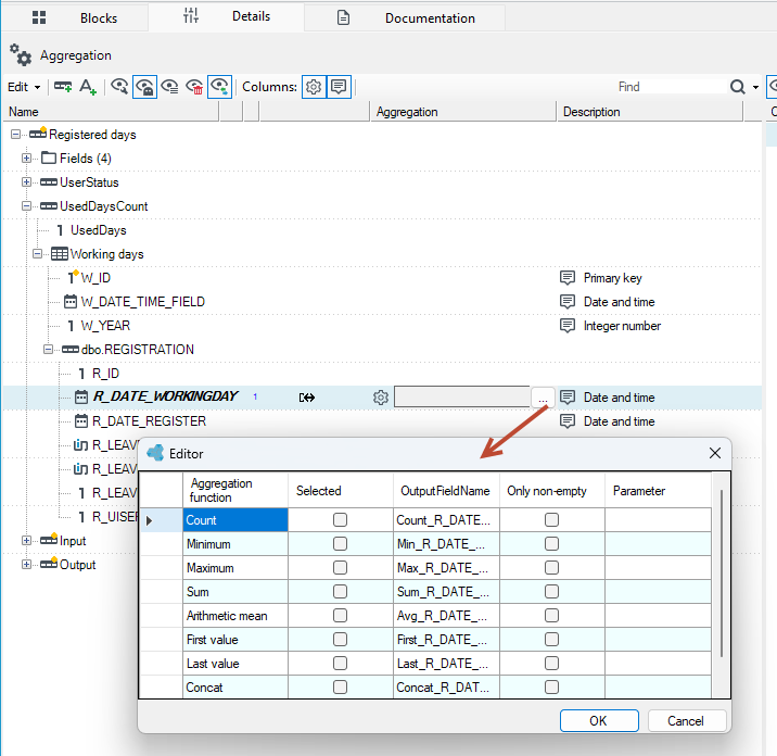
- In order to select an aggregate function and a method of empty values handling, the User should click on the text Aggregation: and then on the button
...what will result in displaying the aggregation configuration window. - After an aggregate function and a method of empty values handling have been selected, the User should close the window with the button x located in the top left window corner.
- By default, there is only one resulting value for each field selected for aggregation. The resulting value is determined using all the values which this field took during the processing phase of the package the aggregation block belongs to.
- It is possible to divide such value set into smaller ones according to the value of another field and then such groups may be aggregated. It enables e.g. calculating bank accounts in each branch of a bank separately.
- To make such a division, one should select the field according to which division should be made using the annotation Aggregation key. It possible to use many annotations like this - the result will be making a division according to the combination of all key values on the path from the aggregated field to a data schema root.
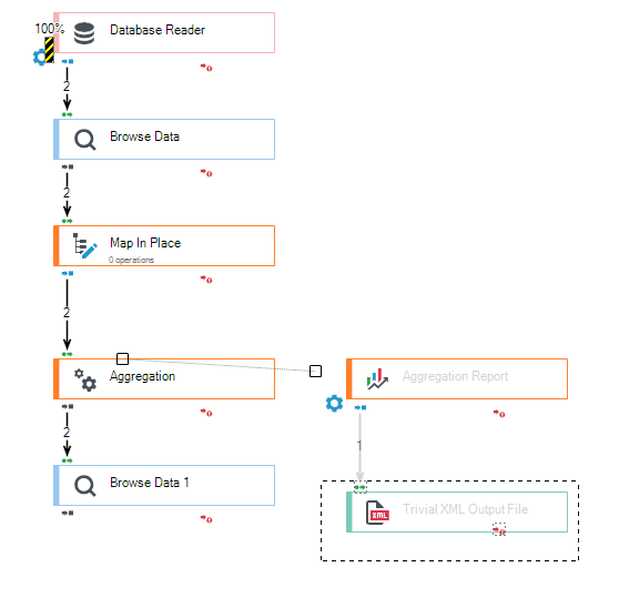
- Original records which have not been changed in any way are directed to a block output. Aggregated values may be fetched from the output of the additional block Aggregation report.
- Aggregated values may be fetched at any moment of package processing. However, values fetched during the phase containing an aggregation block are temporary and are calculated from the records which have been processed so far. In order to make sure that the aggregation results concern all records, they must be read in the later processing phase.
An output schema of the block Aggregation report is similar to an input schema, but there are a few differences:
- It contains only the fields marked with the annotations Aggregation or Aggregation key and only records which are on the paths from these fields to a root.
- Fields marked with an annotation of an aggregation with the function Count have a data type changed to a fixed-point number.
- Records in which a field marked with an annotation Aggregation key occurs are multiple records. Other records are single records.
Fields, which correspond with the keys in the output record, contain the key value for which the values in this record and all deeper records have been aggregated. Aggregation results can be found in the fields corresponding with aggregated fields.
There are two methods of reading the results: as a normal input block or by querying. In the first case, a report block will return records one at a time for each key value combination. In the second case, it will return selected data in response to each query.
Queries may take two forms:
- a flat record (without subrecords) containing the fields with names and types corresponding with all aggregation keys,
- a tree record with a subrecord schema which corresponds exactly (including names) with an output schema of the aggregation report block and which contains the fields with the same name and type as the aggregation keys in the appropriate records. A tree record, which contains only the branches with the aggregation key values matching those in a query, is a response to a query. An empty key value in a query means that everything will be returned.
An example package using the Aggregation block might look as follows
Run Code

The block Run Code is used for calling the indicated code on each input/output/passing record or query.
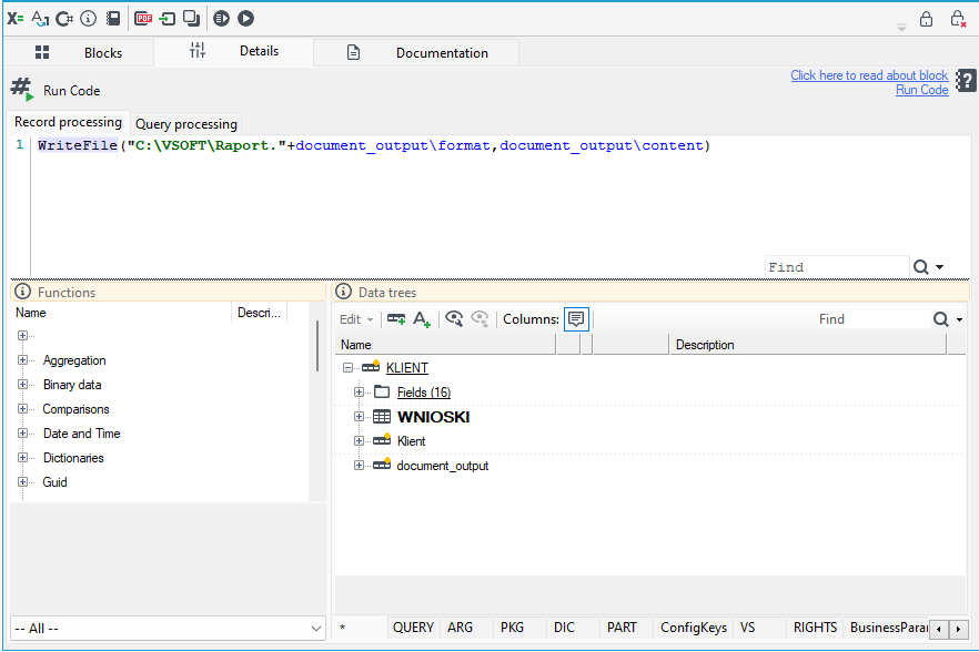
Configuring the block consists of defining an expression in the Input expression property (called for every processed record) or directly in the Record processing window, and, optionally, the Query expression property - Query processing window (called when a query is received - it must return a new query, which will be sent). Both fields are expression editors that support syntax hints via Ctrl+Space, so the block can contain any expression that uses either archITekt's built-in functions or elements from the available data trees/context: QUERY, ARG, PKG, DIC, PART, ConfigKeys, VS, RIGHTS, BusinessParams, LOC, BLK.
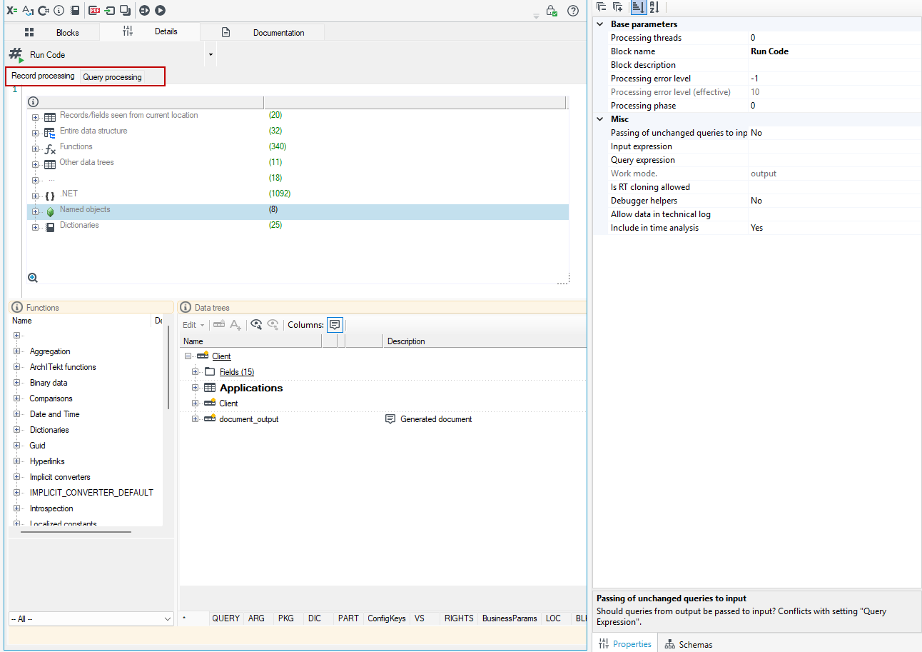
Writing your own .NET code is therefore not required to use the block - in many cases building the right expression out of the built-in functions is enough. For more on how to build expressions, see: Expressions.
- The block should be used for implementing complex business rules and for extending the functionality related to records' processing.
- The block processes records provided by any data source - it does not operate as a data source or a query source.
- The block can be used to set the value of a package output argument using the built-in
pkg.SetArgumentFieldValue()function. This lets the result of the package's execution (e.g. when called from a form) be passed on as an output argument without adding a separate mapping block - see: Package call arguments and Type of actions - Run integration package. - The block can be used to save generated files directly to disk using the built-in
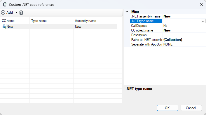
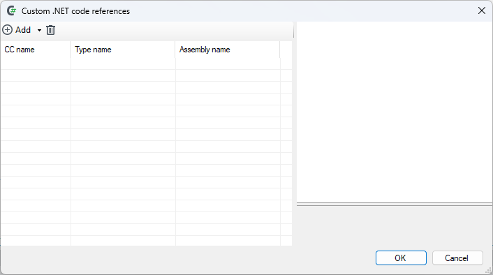
WriteFile()function, e.g. when saving generated documents (normally the results of document generation are saved to binary database fields) - see: Save document. - If the built-in functions are not enough, the block can also be extended with your own .NET code. The first step to configure a block is adding a file/assembly files with additional functionalities. First, you should select the option Custom .NET (cc) code from the menu. The function has been placed in the menu as all blocks Run code may share new functionalities. After the option has been selected, the following dialog box is displayed:

- Add -> From file option should be selected from the menu on the left and then in the dialog box the .NET assembly files which contain methods extending record processing possibilities should be chosen.
- Next, the CC object name attribute (which will be used in the block Run code) should be defined in the tab Properties and a .NET type name which contains methods used for data modification.
After the above mentioned steps have been performed, the added .NET methods will be available in the same syntax hint window (Ctrl+Space) as the built-in functions, in all Run code blocks of the given package.
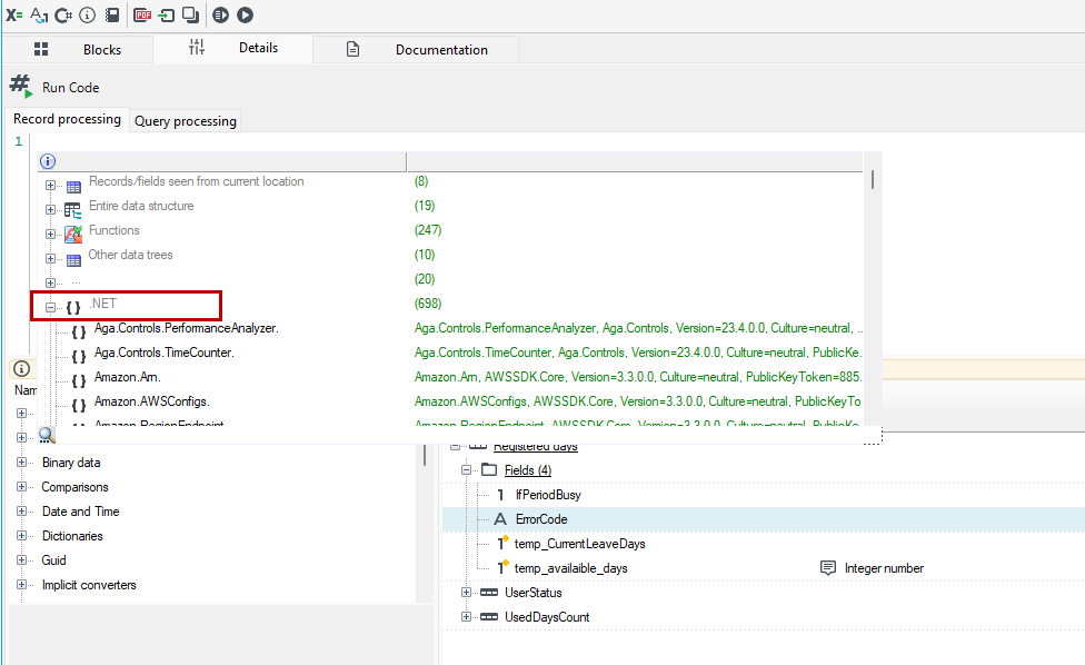
The method will process the system records if base (VTS2.Base.dll) system assemblies have been attached while creating a .NET assembly and a data processing method must take a DataRecord type from this assembly as one of its arguments.
Pivot

The Pivot block is used for performing operations of data inversion which is given as a field name (and possibly a path to it) and a value.
Principle of operation:
The block inserts the value given in one of the input record fields to the field indicated by a path composed of the other fields' content. The most basic example of such operation is changing the collection of pairs "field", "value" into a record with field names given in "field name" and values of these fields in "value".
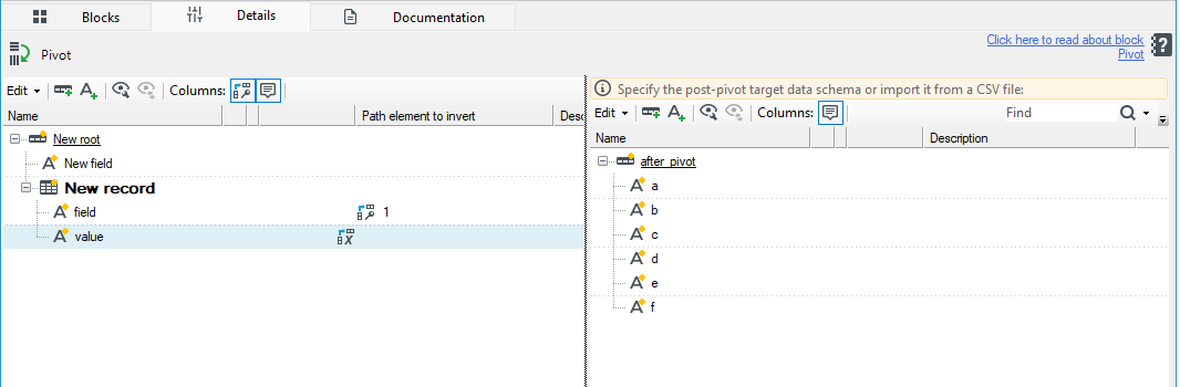
- On the left-hand side, the input data structure is displayed: a record New record is a multiple record which contains the pairs: field, value.
- On the right-hand side, a record to which data will be copied is shown. It is a single record in which field names (a to f) are all the values the field "field" may take in a record on the left-hand side.
A more complex example may be the situation when a field to which data should go is defined by more than one field in input data. An example may be a CSV file which has the following columns: Schema, Table, Column, Value:
| Schema | Table | Column | Value |
|---|---|---|---|
| dbo | Test_table | Column_1 | John |
| dbo | Test_table | Column_2 | likes |
| dbo | Test_table | Column_3 | candy |
The above table will be transformed into one record with the path after pivot\dbo\Test_table which has three fields: Column_1, Column_2 and Column_3. The values: "John”, ”likes” and "candy” will be inserted to the fields of this record.
The record will have the following structure:
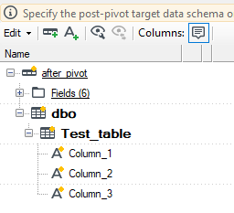
- The above example proves that a certain number of input records (which equals the number of fields in the output record which has to be filled with data) is necessary to create one output record.
- Such collection should be provided in an input record in the form of a multiple record in a schema tree (a root cannot be this record).
- Each input record which contains such collection will be processed separately. A collection of records for one output record may be created e.g. using a normalizer.
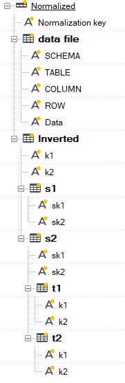
The above example presents only one output record. In reality, you will need to create the entire collection of output records from the data in only one input collection (such as a nested table with a few child records). In input records, there must be a field which contains a unique identifier (within its collection of records) which is used for differentiating output records. Additionally, an input collection should be sorted by the entire path excluding its last element, including an identifier field - in the above example, sorting would be done by the fields 'Schema', 'Table', 'Id'.
The block may create any structure composed of records and fields - including the fields attached to an output collection root. An output collection will be attached as a sibling to an input collection in the output record and such modified record will be an output record of the block Pivot.
| Exemplary input schema | Exemplary schema of inversed data | Output schema |
|---|---|---|
 |  |  |
Block configuration
The block can be found in the toolbox in the section Transformation blocks and it requires connecting both input and output.
- To configure it, an input must be linked so that an input schema is available.
- The block editor consists of two windows used for schema editing:
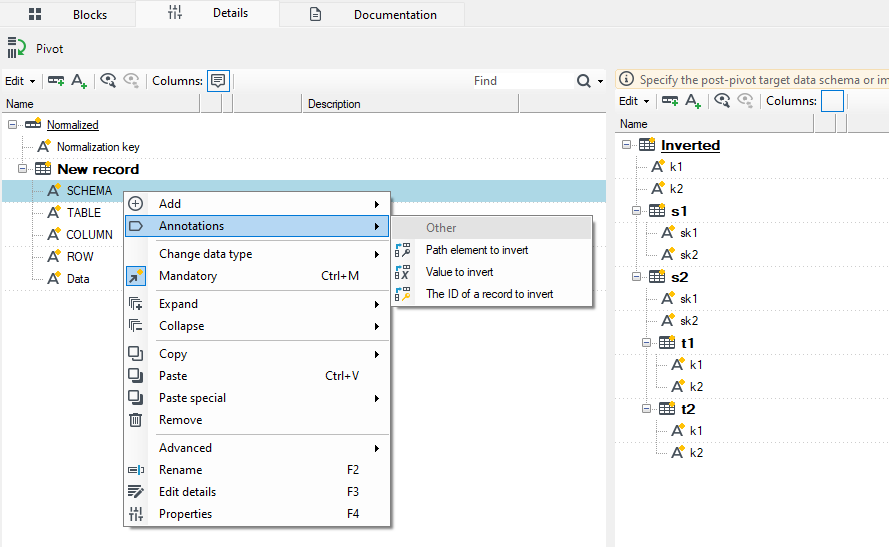
- In the left window, the input data schema is displayed. Annotations should be used to indicate fields which contain path elements (the annotation Path element to invert), a value (the annotation Value to invert) and a record identifier (the annotation The ID of a record to invert).
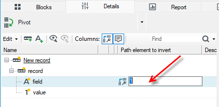
- If an annotation Path element to invert is added, it should be edited and the number of the element to the path should be entered. These numbers must form a series starting with 1.
- All annotations must be on the fields of the same record and the fields must be text fields.
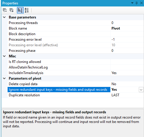
- If a path built of the values of the fields marked as path elements indicates a field which does not exist while processing, the record currently processed will be directed to the error output. In order to ignore such cases (if we are interested only in some fields of the greater number of fields of input data) the value of the block property Ignore missing fields and output records should be changed to Yes.
- By default, input data is not changed during block activity. In order to delete records which value has been copied to an output record, the value of the block property Delete copied data should be changed to Yes. As a result, only records which values have not been written to an output record because a proper field or a subrecord is missing in it will remain in the collection of input data records.
- On the right-hand side, you should enter a data schema after the inversion. It may be done manually by adding fields and records or using automatic schema building.
- The element names in a schema must correspond with the values which will appear in the input data - number 1 corresponds with the elements under the root.
- If there is no value in one of the path fields in the input data, the field is skipped and the path is shorter.
- If there is no element in the path, an error will occur.
- A root record should be marked as multiple if fields which belong to different data records (differentiated based on the value of the field marked with an annotation The ID of a record to be invert) may occur under the root (a path length is 1). Otherwise, an error will occur while loading data.
- Also, fields which will not be filled with input data may be added.
- The fields to be filled must be text fields.
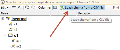
In order to use automatic data schema generator, the User should:
- Prepare a CSV input file containing only the columns which will constitute the path (the elements should be marked with annotations Path element to invert), a column separator should be „|” and no heading must occur.
- Create a new record, under which a schema will be created, and then select it (or select any existing one).
- Click a button Load schema from CSV file and select the file the User has prepared.
- Loaded schema may be edited freely.
For example:
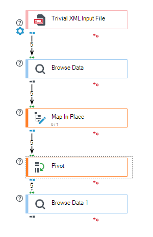
- Create a processing package using the Pivot block.
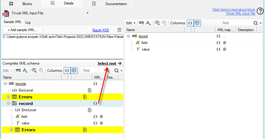
- Load the data in the Trivial XML Input File block. Click the Add sample XML button, then move the record to the right side.
The file contains the following data:

<?xml version="1.0" encoding="UTF-8"?>
<records xmlns:xsi="http://www.w3.org/2001/XMLSchema-instance"
         xsi:noNamespaceSchemaLocation="records.xsd">
    <record field="quantity" value="1" />
    <record field="weight" value="20" />
    <record field="quantity" value="3" />
    <record field="weight" value="40" />
    <record field="quantity" value="5" />
</records>
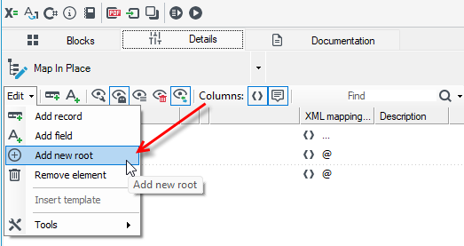
- Add the Map In Place block and, in the block details, add a new root. Click the Edit menu and select Add n ew root.
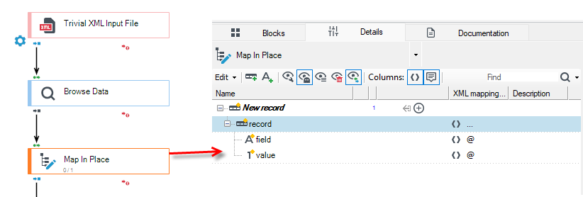
- The collection of records to be reversed cannot be the root of the data schema, so in the Map In Place block, either add a new root or move the data to be reversed to a record further down in the data schema.
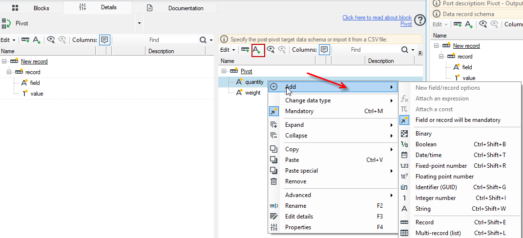
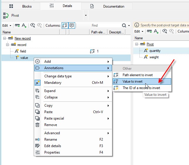
- Add the Pivot block. In the right part of the window, specify the target data schema. Add the new fields quantity and weight using the contextual menu or the options from the top toolbar.
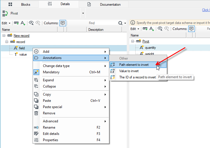
- Add the annotation Path element to invert.
- For the value field, add the annotation Value to invert.
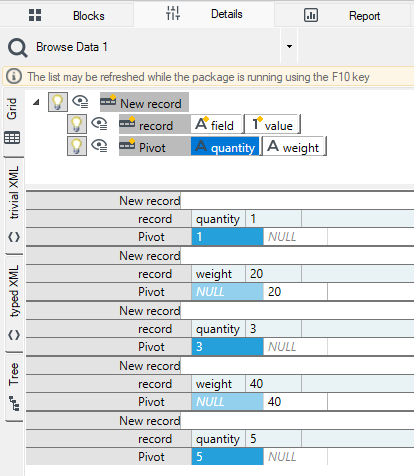
- Add the Browse Data block and run the package. As a result of the processing, the data will be correctly assigned to the weight and quantity fields.
Map Copy

The block enables changing a record structure completely on the basis of the original fragment of the analysed record.
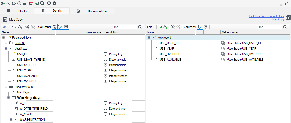
- The block enables changing a record structure completely.
- The detail window has been divided into two parts. The first part is an input data structure preview and the second one enables creating a copy of structure copy based on the original.
- The User may copy the original structure elements by dragging records/fields between windows or by adding tree fragments individually.
- An annotation Value source enables returning the path to the original place in the structure.
Operations on particular tree elements have been described in details in the chapter devoted to adjusting record schema and fields (see: Data processing).
Run code - complex types

The Run code - complex types block is used to call the indicated code on each passing record or query.
In the block, the code is executed by mapping parameters as whole objects. In a simple call, only parameters like numbers or text are passed.
Similar to a regular Run code block, you can add your own method for the call.
- The first step in configuration is adding the assembly file(s) with additional functionalities. To do this, select the option External .NET Code (cc) from the top menu package.
- From the left-hand menu, choose Add -> From File, and in the file selection dialog, choose the .NET assembly files that contain methods extending the record processing capabilities."
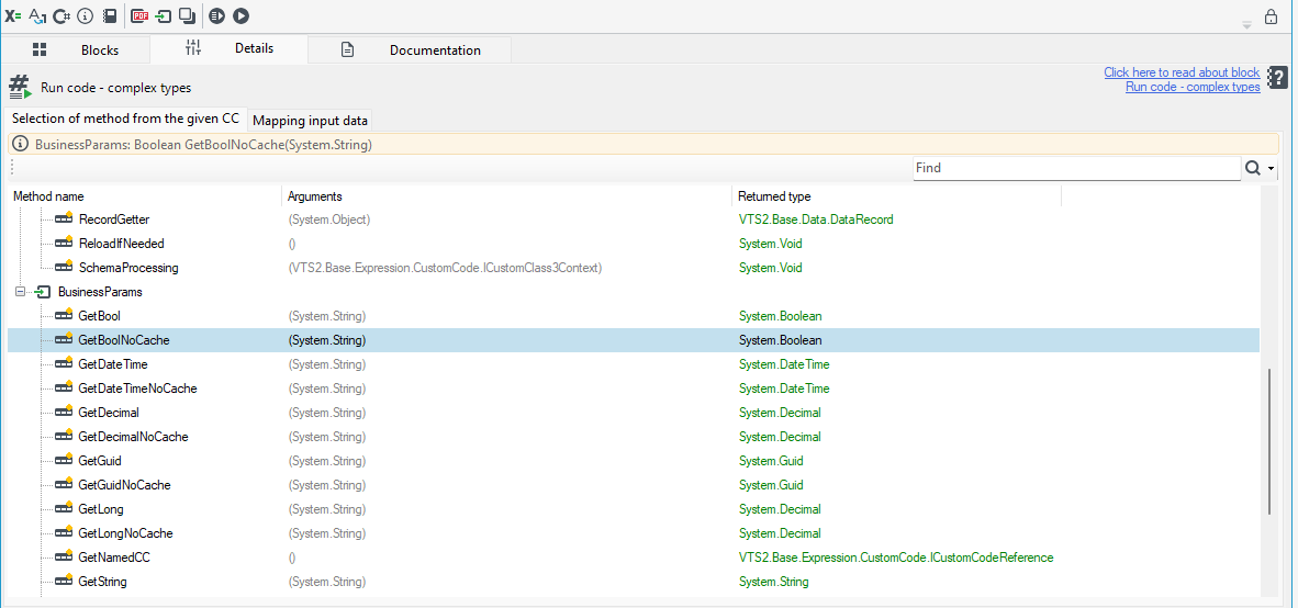
- In the Selection of method from the given CC window, double-click to select the function.
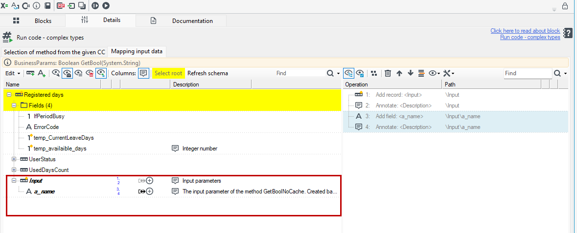
- On the Mapping input data tab, perform the mappings.
- First, select the data root. Mark the record on the data diagram and press Select root. A grayed-out Input record will appear along with other input parameters of the method."
- Perform the mappings for the method's input parameters. You can drag fields from the data schema to the method's fields and select Set as the value source from the context menu."
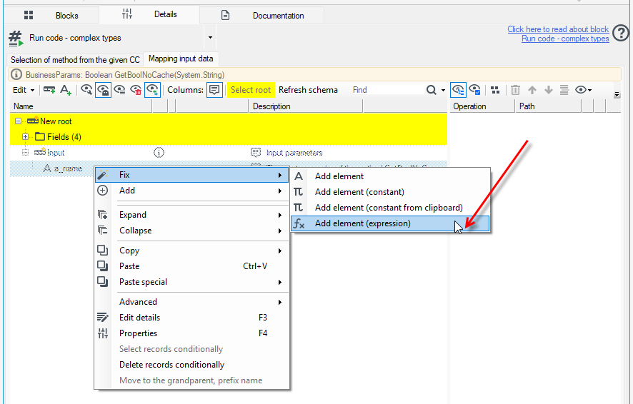
- You can also use annotations and set the value for a field using an expression, constant, etc.
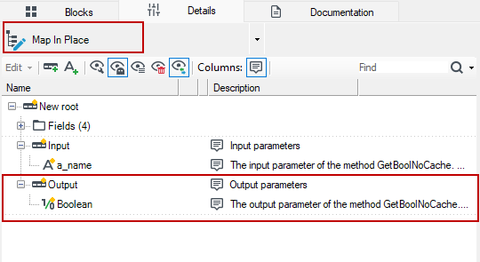
- If you add another block after the code execution block, for example, a Map In Place block, the Output record will be available, containing the method's output parameters. This diagram is previously available for preview in the Schemas panel.
For example:
Create a processing package that retrieves values from a defined business parameter using the Run code - complex types block.

- Define the business parameter - see: Creating New Parameters.
- After defining the parameter, we will be interested in the Key and the parameter type - Data type.

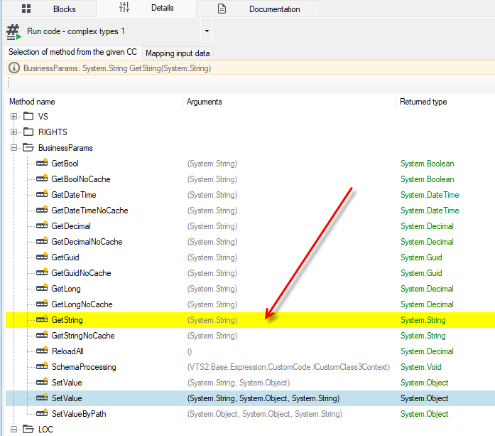
- Add a Random Data Generator block, then a Run code - complex types block. Go to the block's details and double-click to select the
GetStringmethod from theBusinessParamstree. This is the method that retrieves a text value from the defined business parameters.
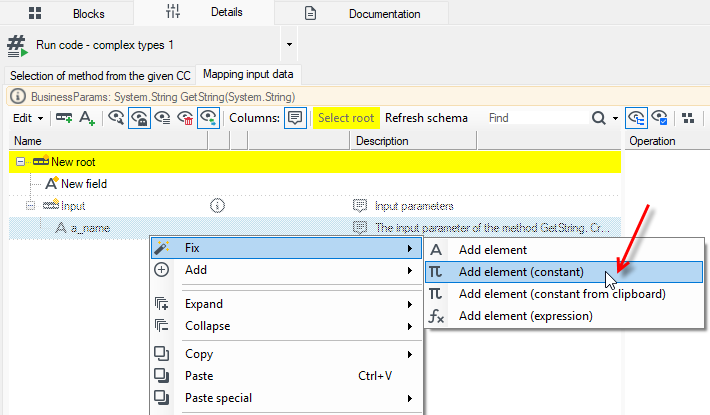
- Go to the Mapping input data window, select the record, and press Select root.
- Select the a_name ghost and choose Fix>Add element (constant) from the context menu.
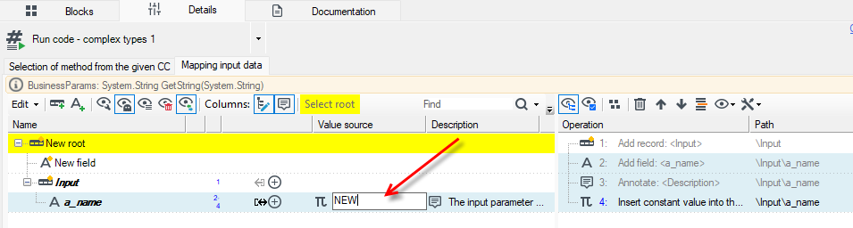
- In the Value cource field, enter the parameter key name. In this case, it’s NEW.
- Add a Browse Data block and run the package. In the data preview, the Output record should contain the value of the defined business parameter.