Workflow elements - activities
Create a data element
- The action creates a new instance of the data object. For the activity, you need to indicate the variable to which the created object will be assigned, i.e. earlier it is necessary to define the Variables for the workflow, see: Defining the variables.
- Due to the fact that it is a database operation, the type of the workflow variable must be a data structure.
- Drag an activity from the Toolbox onto the canvas and link it to the rest of the activities.
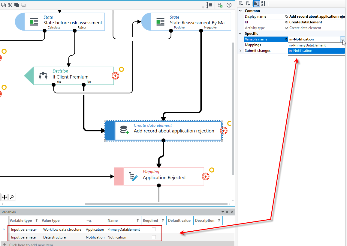
- Select the type of data you want to create - in the Properties panel, select an option in the Variable name field. In the case in the figure below, you can choose from 2 data structures that have been defined in the Variables panel.
- The data structure of the workflow is treated as the main structure of the workflow and always has the name PrimaryDataElement and cannot be changed.
- Save the workflow and run it.
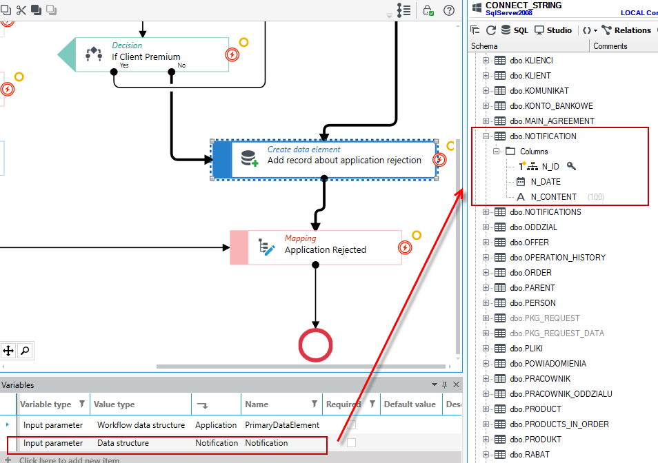
- After starting the workflow, activate the Databases panel, find the data structure in the database, and open the SQL query editor.
- Run an SQL query to verify that the entry was created.
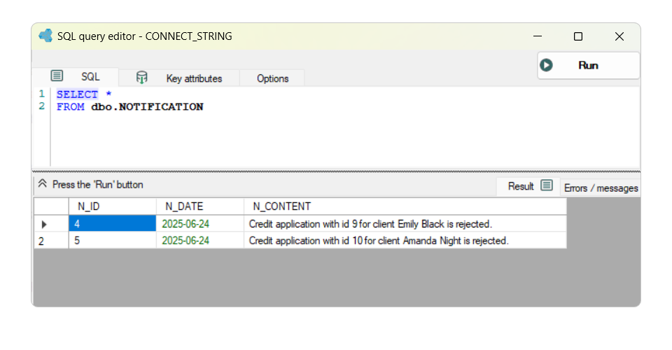
In the above example, after the user rejects an application, the information is saved to the Notification table with the date of the application status change and information about the rejection and the client concerned.
- Go to the Mappings property of the activity.
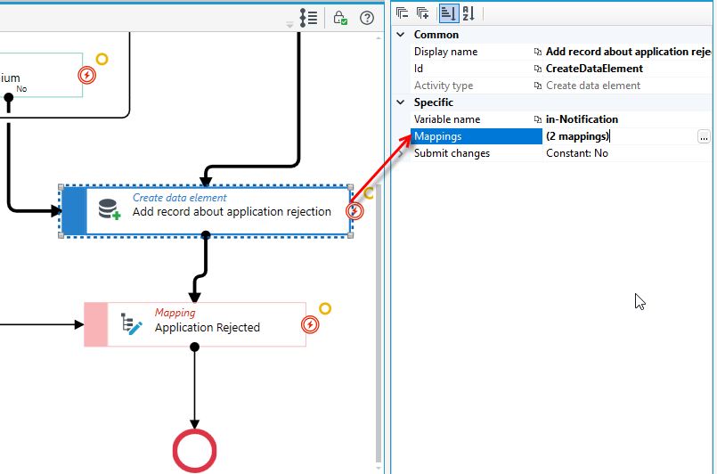
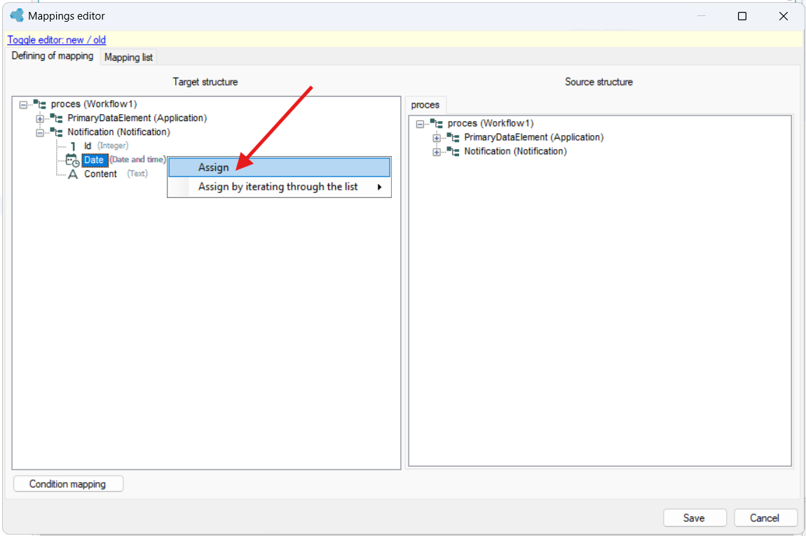
- Specify the mappings for the Date and Content fields. Right click on the field and select Assign.
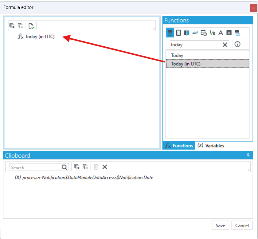
- For the date field in the formula editor, search for the Today function and drag it onto the formula node.
- For the returned message content field, define the message. The following example uses the Concatenation function.
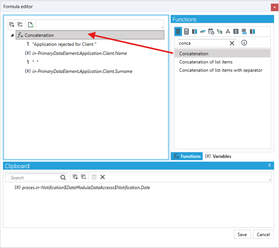
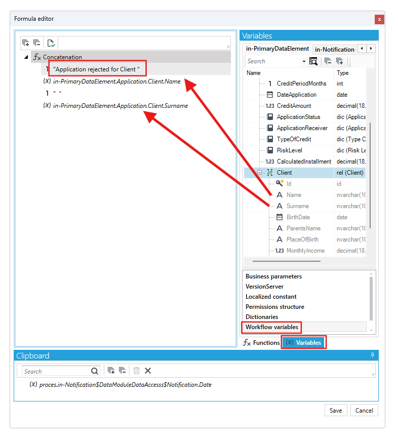
- In the following arguments of the Concatenation function, enter the message content. In the example below, the content of the message is the constant text "Application rejected for Client" and, in turn, the name of the client in the context of which the workflow was processed.
- Go to the Workflow variables tab and from the in-PrimaryDataElement (that is, the main structure for the workflow) drag the Name and Surname fields into the subsequent arguments of the function.
Check point
The Check point activity saves data in the database and closes the transaction associated with the execution of a part of the workflow. In other words, it is the point of automatic transaction approval.
The operations performed within the workflow are performed in a single database transaction that starts when the workflow is started or continued and ends when the workflow ends, goes to sleep (reaches a State activity) or reaches a checkpoint. At the moment of achieving the checkpoint, the current transaction in the database will be committed, having saved all variables in the workflow to the database, and then automatically a new database transaction, covering a further part of the workflow, will be opened.
- Drag an activity from the toolbox onto the canvas and link it to the rest of the activities.
Mapping
The Mapping action allows you to assign the values of variables or selected fields in the data structure using values stored in other variables or fields or by using a formula mechanism that allows you to calculate it.
- Drag an activity from the toolbox and link it to the rest of the activities.
- Double-click on an action (you will be immediately redirected to the mapping editor) or select an action and in the Properties panel, in the Mappings section, select the button
 and go to the mapping editor.
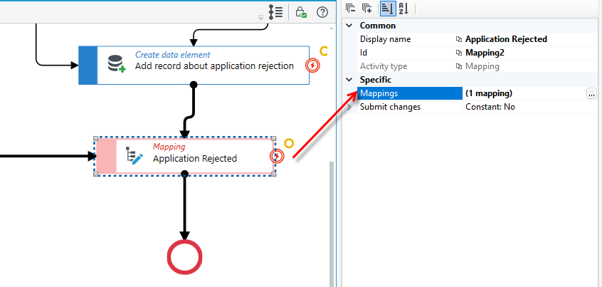
- In the window that appears, specify the mapping.
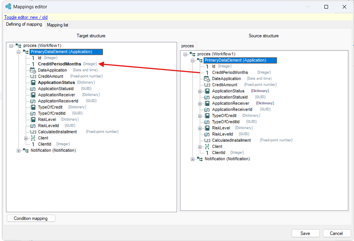
- The source structure is the original structure that has been specified in the variables, so it can be the entire data structure or local variables that have been added, or individual input and output parameters. The data is taken from it.
- The target structure is the structure on which the actual mapping takes place and to which the values are saved.
- You can use ‘drag and drop’ to assign a value from the given field in the source structure to a field in the target structure.
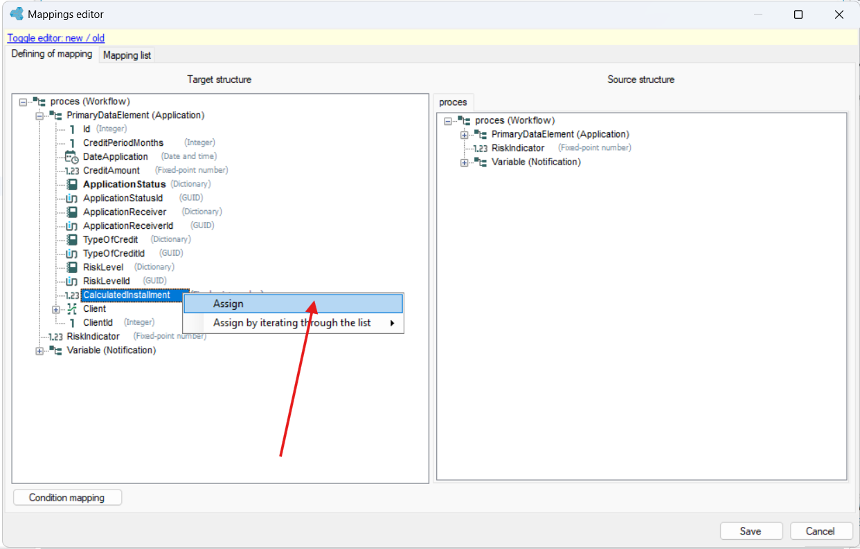
- If you want to specify a more complex mapping, e.g. return a computed value or a dictionary value in the field, right-click on the field where you want to add the mapping and press Assign.
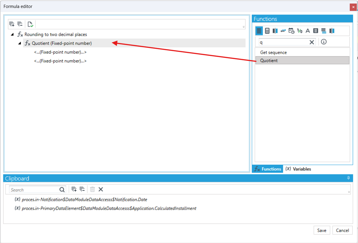
- The formula editor window will open, where you can define the formula using the available functions (arithmetic, compare, converters, date and time, logical, text, lists and others).
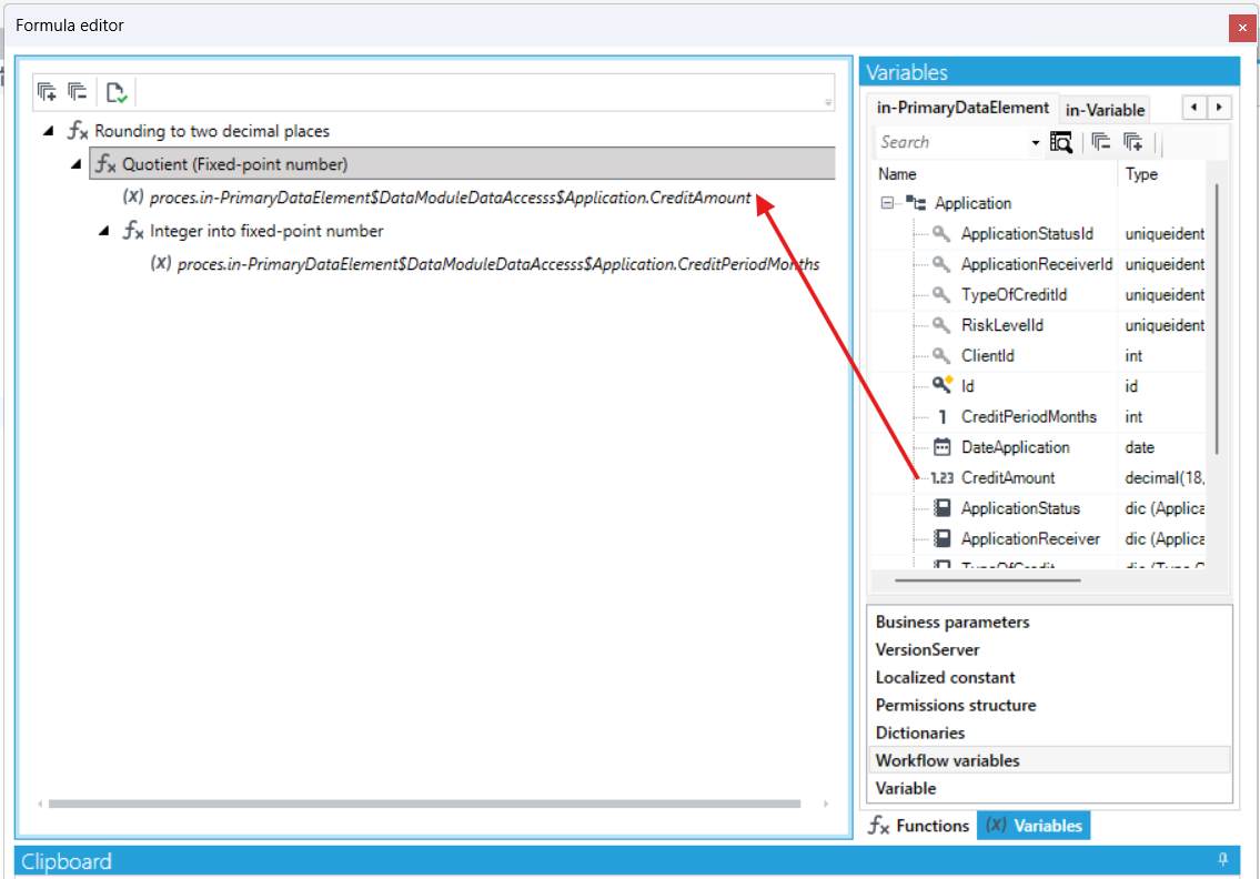
- In the following case, the credit installment is calculated and the quotient is returned rounded to two decimal places. Search for the Rounding to two decimal places function and then the Quotient function and drag it to the formula node.
- Go to the Variables tab and select Workflow variables. Drag into the formula those fields that are to be divided. In this case, these are the fields CreditAmount and CreditPeriodMonths.
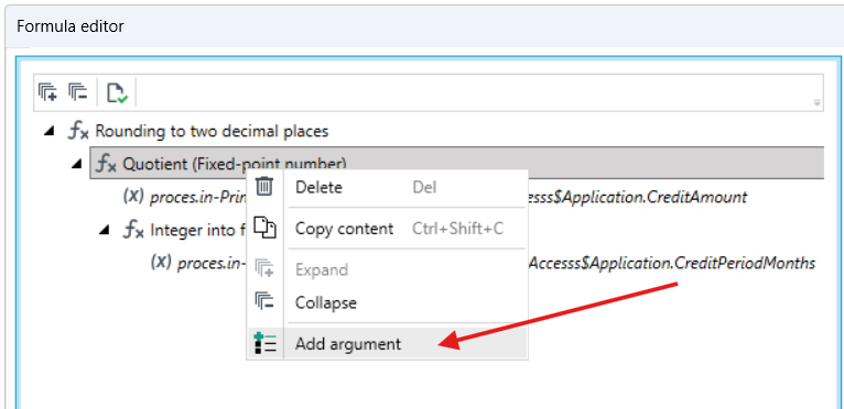
- If you want to add another item/argument to the formula, right-click the formula node and choose the Add argument operation.
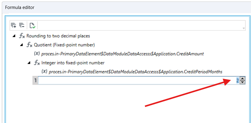
- In the new argument, you can assign a field from the workflow data structure as in the previous case, or double-click and enter a value.
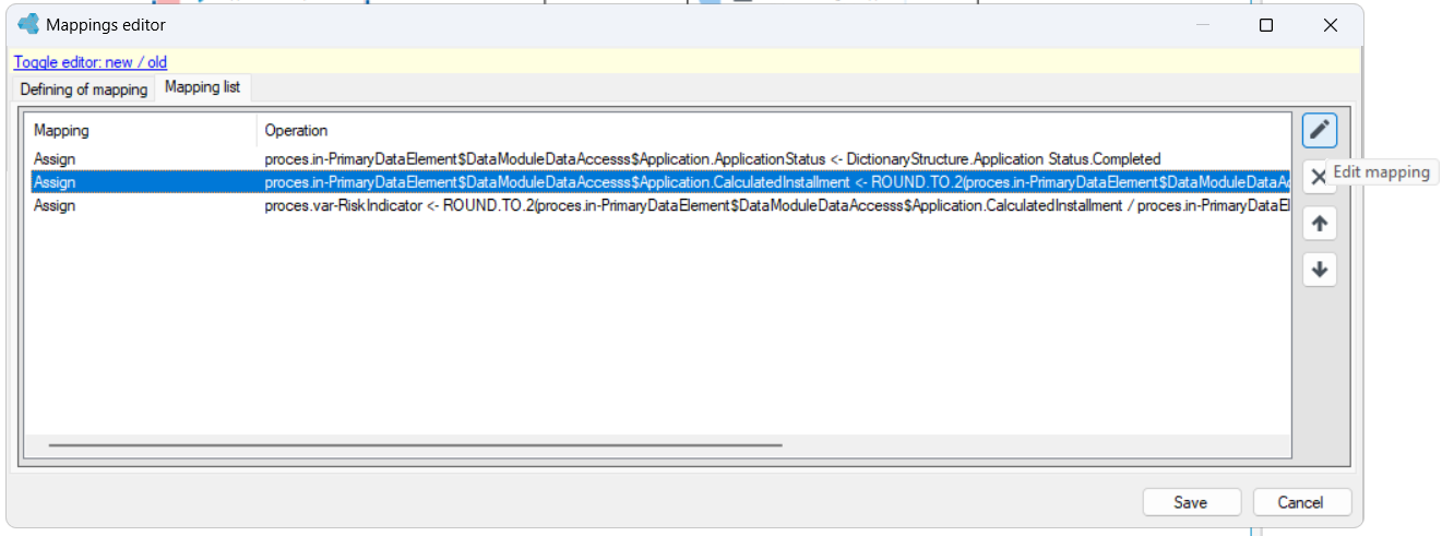
The list of all mappings is available on the Mapping list tab, from which you can edit or delete a given mapping.
All mappings are performed before the data is saved to the database. If an exception occurs during the execution of subsequent mappings, no information will be saved to the database. The order of the mappings is not irrelevant. It matters when one field in the structure takes on the value of another, and then the field that was the data source changes its value.
Conditional mapping
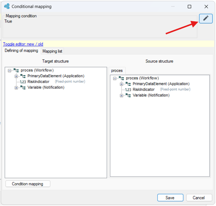
When specifying a mapping, you can also enter a conditional mapping. This option is useful when the same mapping should be entered for several fields, but only if the same condition is met. By default, the condition is set to True, which means that the mapping is always performed.
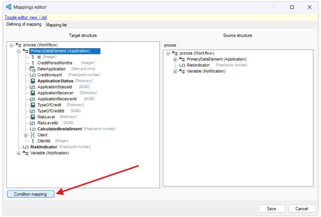
- Go to mapping from the Properties panel.
- In the Mapping Editor window, select the Conditional mapping button.
- Enter the condition in the Conditional mapping section. Select the buttons to go to the formula editor.
State
The State activity allows you to define:
- a form that will be displayed to the user of the application when the workflow reaches a given step,
- a list of output ports, i.e. exits from the activity - the action code (any string) is entered for each of the output ports. If the Continue workflow action is performed on the form (e.g. by pressing a button) and passes the action code to the workflow, the workflow will exit with the appropriate port.
For example:
If you define a form on which you can accept or reject the data, then in the State activity you must specify 2 outputs corresponding to a positive or negative business path.
Before starting the configuration of activities, create a form that will be used in the workflow.
- Drag an activity from the toolbox and link it to the rest of activities.
- Go to the Properties panel and pin the form in the Preview form section.
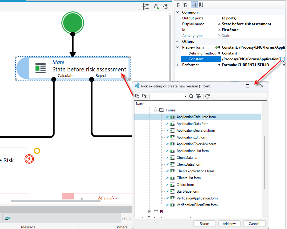
- Then specify the number of output ports. Select the button in the Output ports section.
- In the Ports editor window, select Add > User action output and enter the action name and code.
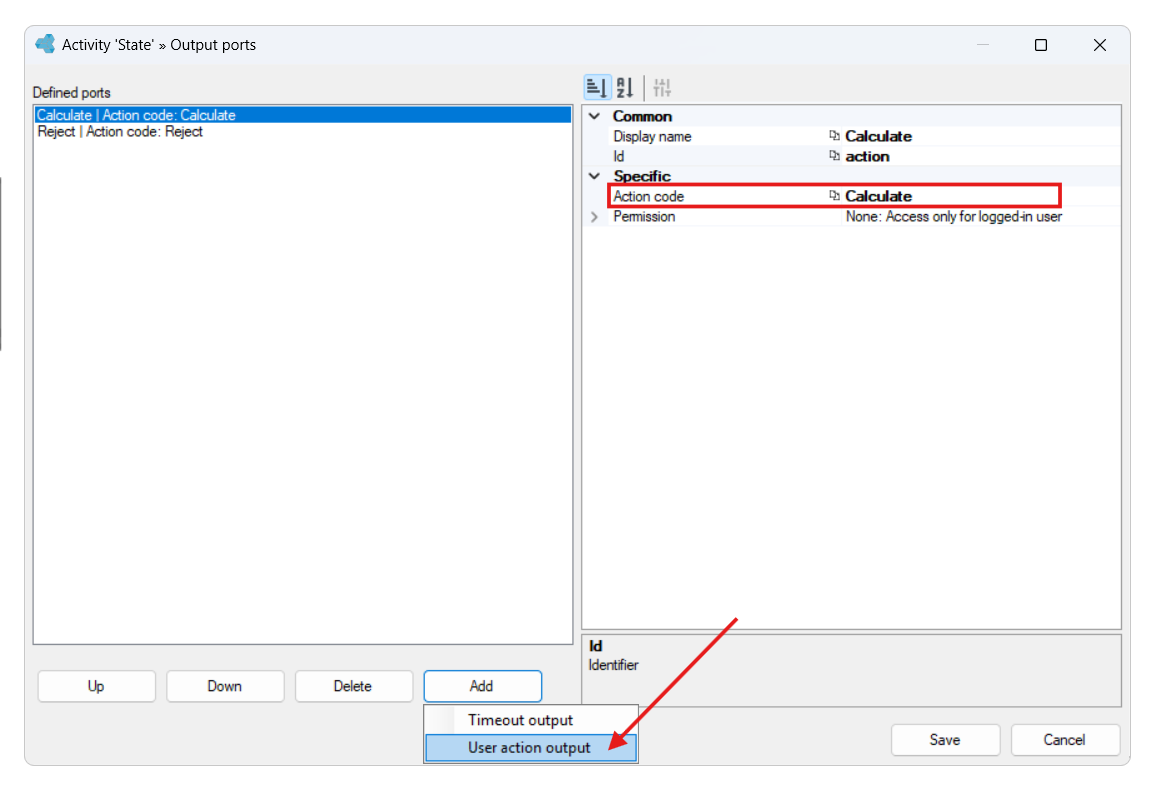
The action code entered in the workflow should be entered in the definition of the Continue workflow action on the form. Depending on the action code received, the workflow will then follow the chosen path.
In the configured activity shown in the picture above, 2 outputs are defined. The workflow will continue if it receives one of the defined action codes: Calculate or Reject.
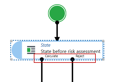
For example:
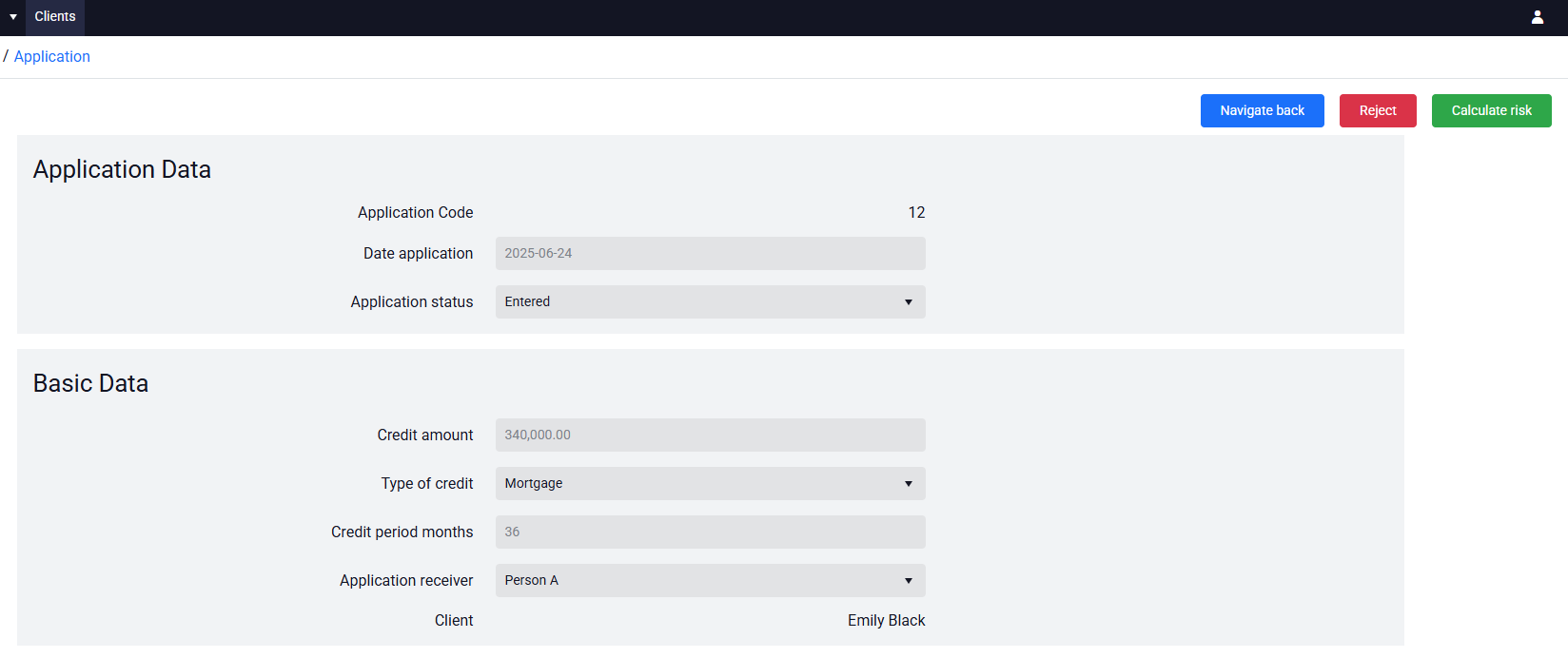
- A form with actions has been defined, on which the user decides whether to confirm or reject the data.
- When configuring the action in the form designer, the workflow is attached and the indicated action code determines which path the workflow follows (Action code Calculate or Reject).
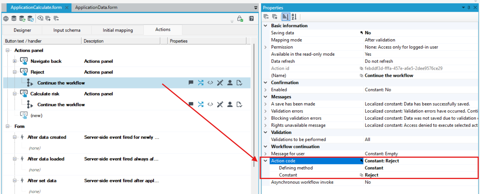
- In the example below, the same workflow has been attached to each action, but different action codes are indicated to distinguish between positive and negative paths.
Timeout
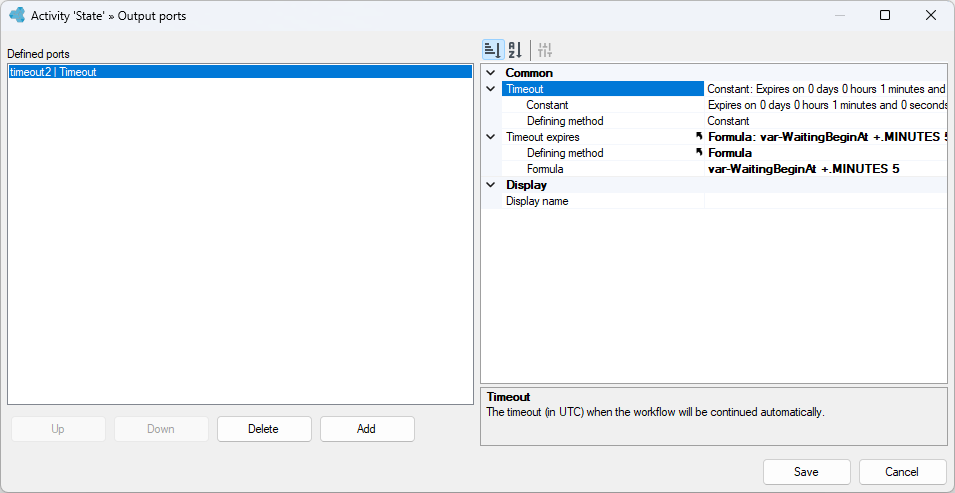
You can specify the timeout output and configure the moment when the workflow is resumed. If you use the Timeout option, note that it treats the configured value as UTC time.
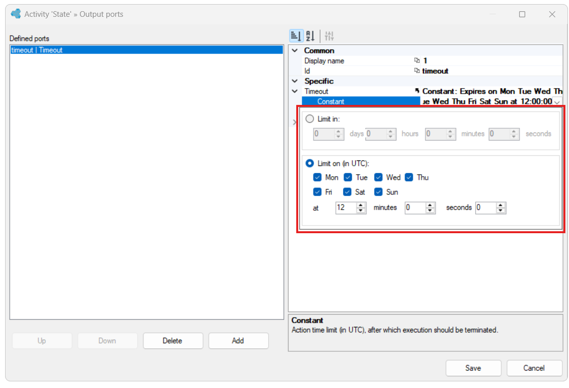
Application timeout output for integration with other systems
If, at a certain stage of the process, you want to wait for the end of the operation in the external system, you should add a timeout output to the State activity (e.g. every 30 seconds), directing to the activity that queries the external system:
- If a satisfactory answer is obtained, process control should be redirected to the next steps.
- If there is no response, the control should return to the same state.
If the waiting for operation in an external system should be time-limited:
-
for the timeout output, define the Timeout expires property and use a formula to assign it the maximum time after which the timeout output will cease to be valid,
-
add a second timeout output with the Timeout property equal to or later than the Timeout expires property of the previous timeout output - the process will exit with this timeout output when the waiting time for action execution in the external system expires.
See how to define a form and attach it to the State activity
Building a form and linking to the workflow
Decision
For the Decision action, as well as for the State activity, you can specify multiple output ports. The decision element makes it possible to choose the path of the workflow, depending on the conditions specified in the activity. The user's task is to define the conditions that must be met and to indicate the output that should be selected.
There are two types of ports:
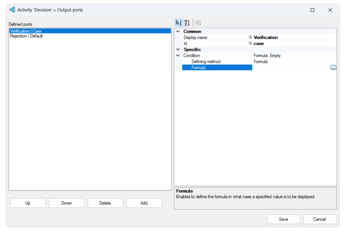
- Conditional output - the workflow will exit via the given port if the condition is true.
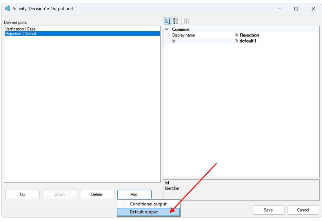
- Default output - the workflow will exit through this port if none of the conditions on the previously defined outputs are met. This output should be the last one in the sequence.
The conditions are checked in the order they are listed. The workflow will exit with the first port for which the condition is met.
- Drag an activity from the toolbox and link it to the rest of the activities.
- Then specify the number of output ports. Select the button in the Output ports section.
- In the Ports editor window, select the Add > Conditional output or Default output button depending on whether you want to enter a condition for one of the outputs.
- If you selected Conditional output, go to the Condition section, then the Formula editor and enter a condition.
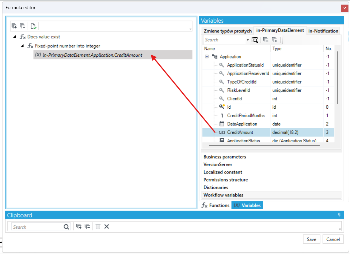
- In the formula editor window, drag the function you want to use and then configure its arguments. In the following case it is checked if the value of the CreditAmount does exist.
- Add another port and select default output.
- Name the ports.
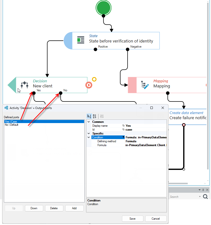
Below is an example of a configured action Decision with 2 output ports. Depending on whether the client is a new user (conditional exit) or not (default exit), the workflow will continue to follow one of the paths specified in the action.
Remember to add input and output parameters if required by the condition configuration in the activity.
Asynchronous and synchronous workflow
The use of these activities allows you to start other workflows from the level of a given workflow.
If you use the Asynchronous workflow action in the main workflow, the newly started workflow will run simultaneously to the current workflow. After a new workflow is started (initialized), the activity will continue with the steps of the main workflow.
The asynchronous workflow will be executed completely independently of the main workflow. No relation can be assumed between the time of execution of individual steps of these two workflows.
If you want to synchronize the execution of simultaneous workflows, use the Waiting for a workflow activity (see: Waiting for a workflow).
- Drag an activity from the toolbox and link it to the rest of the activities.
- Go to the Properties panel and select the workflow you want to run.
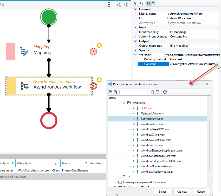
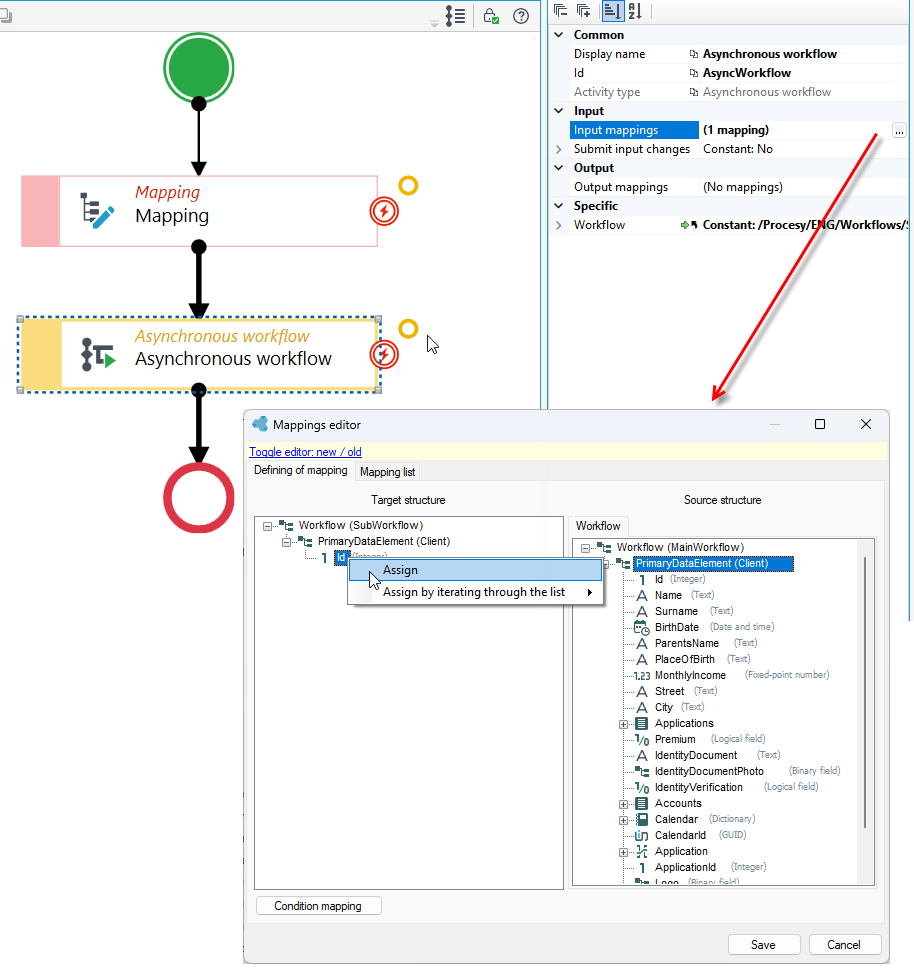
- For both asynchronous and synchronous workflow activities, you can additionally define input and output mappings.
- Select the button
...in the Input and Output mappings section and add the mappings. - In the mapping editor, specify mappings. Use the simple field value assignment or the advanced option and go to the formula editor. The principle of operation is described in the Mapping activity.
Separate subworkflow outputs
In the Synchronous workflow activity, you can handle each way the subworkflow ends separately. When this option is enabled, each End element of the subworkflow becomes a separate output port of the activity in the main workflow. This lets the main workflow follow a different path depending on how the subworkflow ended.
This option is available only for the Synchronous workflow activity. With an asynchronous workflow, the main workflow does not wait for the subworkflow to finish, so it cannot react to how it ended.
The names of the output ports are taken from the Id property of the End elements in the subworkflow. For example, if the subworkflow has two End elements with the identifiers End1 and End2, the Synchronous workflow activity in the main workflow gets two output ports with the same names.
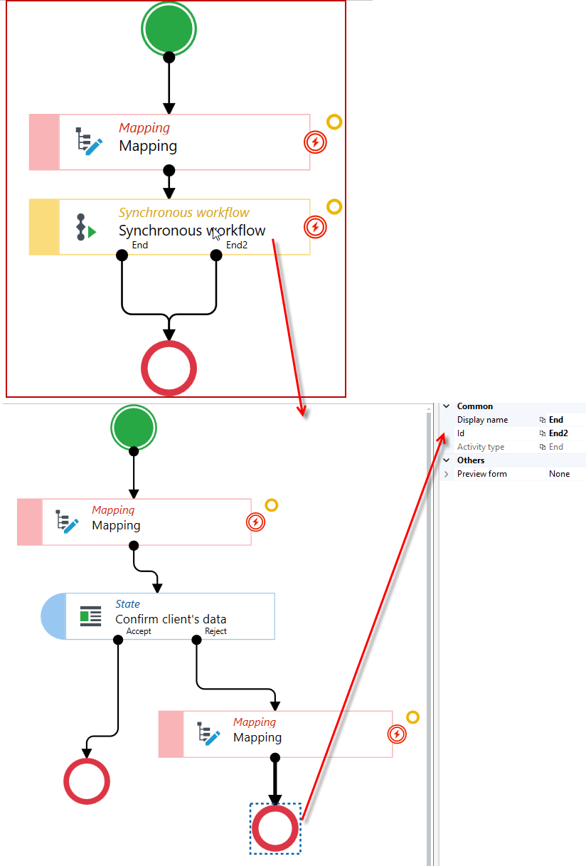
To configure separate outputs:
- Open the subworkflow, select each End element in turn and, in the Properties panel, enter a name describing that way of ending in the Id field, e.g. Accepted or Rejected. This name is shown as the output port name in the main workflow, so it should clearly indicate what the path means.
- In the main workflow, select the Synchronous workflow activity and, on the Properties panel, select Yes in the Split outputs field.
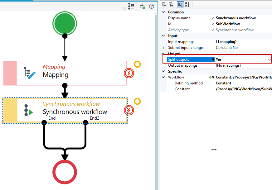
- Connect each output port of the activity to the next elements of the main workflow.
Waiting for a workflow
The Waiting for a workflow activity is waiting for an asynchronous subworkflow.
If you have used an activity in your workflow to invoke an asynchronous workflow, then it makes sense to use a sync activity that will wait for the asynchronous workflow to complete or reach a certain status.
For synchronization activities, it is necessary to provide the instance Id of the asynchronous workflow - this should be included in the output mappings of the activity that starts the asynchronous workflow.
- Drag an activity from the toolbox and link it to the rest of the activities.
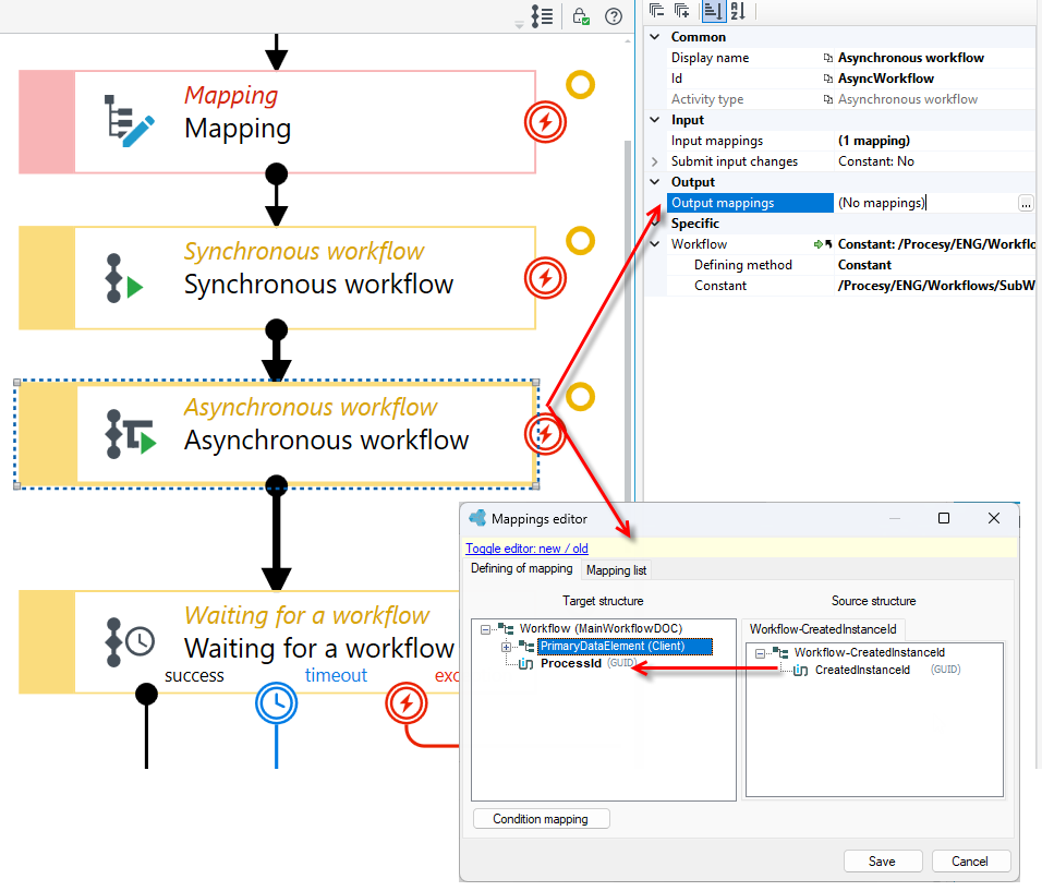
- In the Asynchronous workflow action it is necessary to set the output mapping in which the asynchronous workflow instance Id will be passed.
- In the Variables panel, add a local variable ProcessId of type Guid.
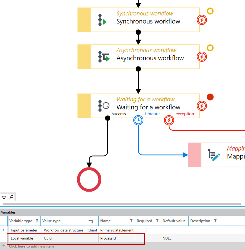
- Go to the Properties panel of the Asynchronous workflow action and select the button
...in the Output Mappings section. - Define the mapping: drag from the source structure CreatedInstanceId to the Guid field that you added in the Variables (ProcessId).
- Now go to the Waiting for a workflow activity. In the Asynchronous subworkflow instance identifier section, in the Formula field, select the button to indicate the instance Id of the workflow the Waiting for a workflow activity should wait for. Here you refer to the ProcessId variable set in the previous step in the mapping of the Asynchronous workflow activity.
- In the formula editor, go to the Workflow variables and drag the ProcessId field to the formula window.
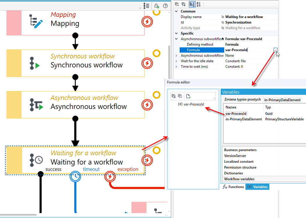
In the Waiting for a workflow activity you can also specify that the main workflow should wait not for the subworkflow to finish, but for it to reach a selected state.
- Select the Waiting for a workflow activity and go to the Properties panel.
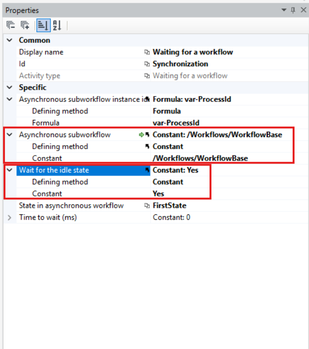
- In the Wait for the idle state field, select Yes. An additional option will be displayed that allows you to select an asynchronous subworkflow.
-
In the Asynchronous subworkflow field, select the subworkflow. The State in asynchronous workflow field will be displayed.
-
From the list in the State in asynchronous workflow field, select the state the main workflow should wait for.
The list contains all State activities defined in the selected subworkflow. Each state is shown on the list under the name from its Id property, not from the Display name field. In the example below, the State activity in the subworkflow has the display name Confirm client's data and the identifier ClientsData, so the list in the Waiting for a workflow activity shows ClientsData.
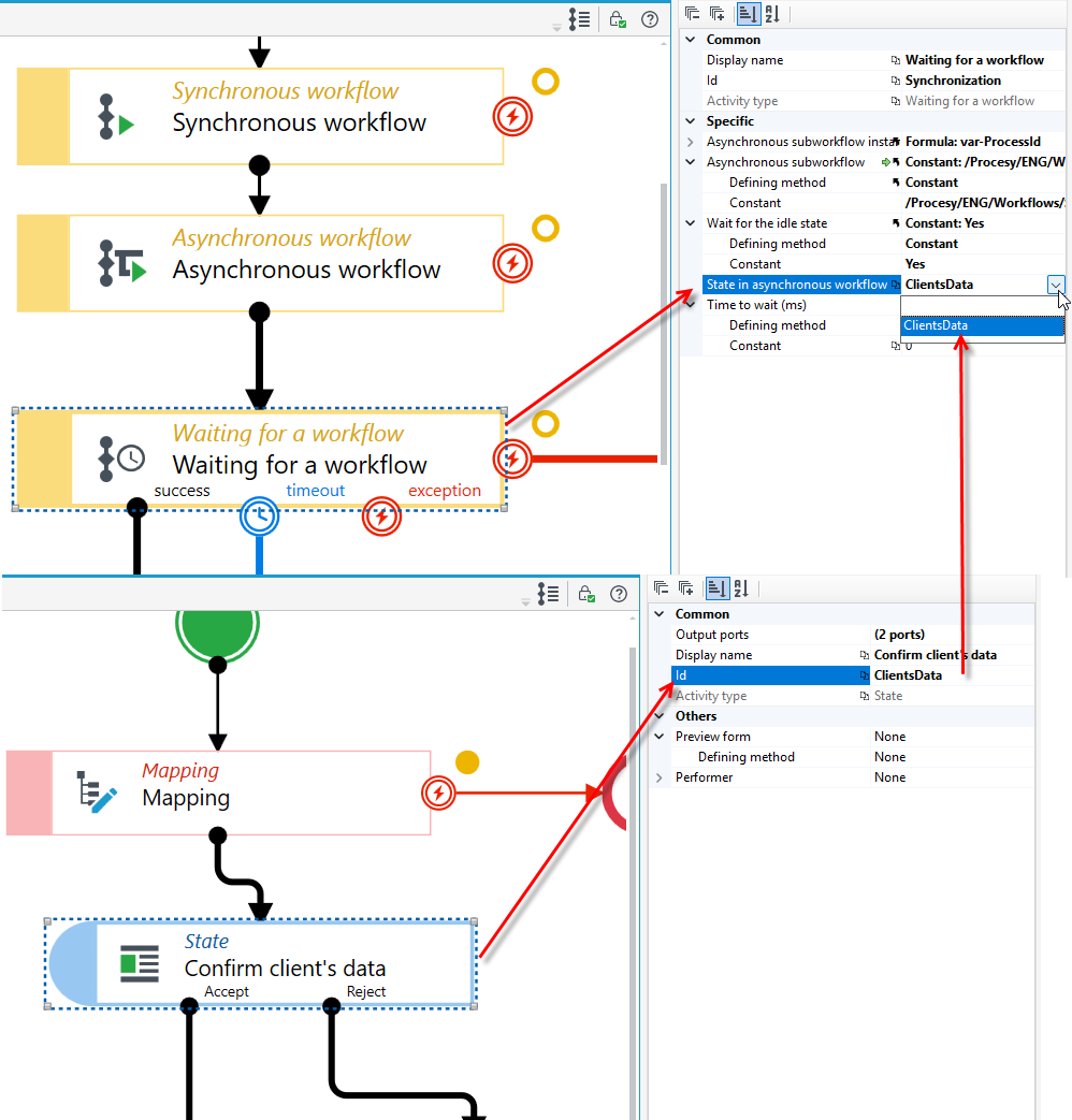
To make the states easy to recognize on the list, give them meaningful identifiers in the subworkflow. Select the State activity in the subworkflow and, in the Properties panel, enter a name describing that stage in the Id field, e.g. ClientsData instead of the default State1.
The Waiting for a workflow activity has 3 output ports by default which you can specify. That is, the behaviour during the correct execution of the workflow, timeout or in the event of an error. All outputs of the activity should be defined and connected with the subsequent elements of the workflow.
If you do not want to specify different behaviours in the workflow in case of an error or timeout, you can connect all outputs with the same activity as in the case of the correct execution of the workflow, i.e. Success.
- To exit the Waiting for a workflow timeout action, you can specify the waiting time for the execution of an asynchronous workflow in milliseconds.
- Select the Waiting for a workflow action and go to the Properties panel.
- In the Timeout section, enter a value (in milliseconds).
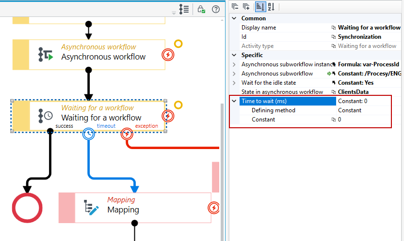
The maximum waiting time is 2 minutes; even if you enter a larger value, it will be reduced to 2 minutes.
Multi-asynchronous workflows
An activity allows you to start several asynchronous workflows at once.
If you want to run several asynchronous workflows, you can define them in one step, without the need to add separate steps for each workflow.
- Drag an activity from the toolbox and link it to the rest of the activities.
- Select the activity, go to the Properties panel and select the
...button in the Activities section.
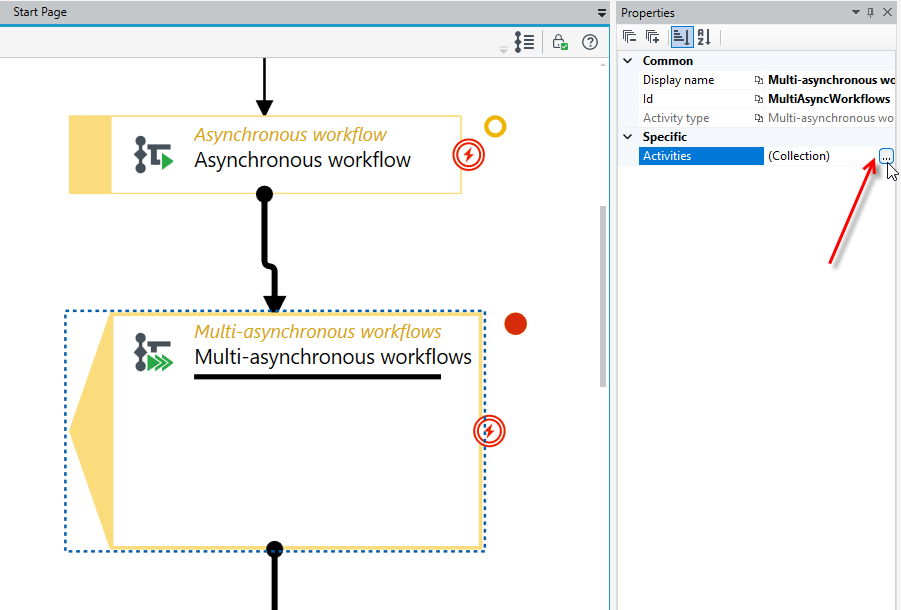
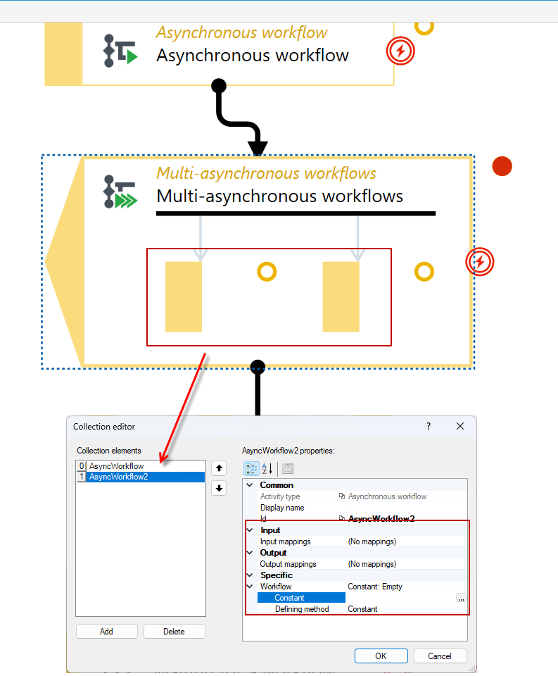
- Add the collection’s items, that is, asynchronous workflows that will be run as part of the task.
- Select the Add button and then, in the Workflow properties, select the path to the workflow that you want to run in the action.
- If needed, specify input and output mappings.
- If you want to add another workflow, select Add and proceed as above.
Multi-workflow synchronization
The Multi-workflow synchronization activity synchronizes the workflows added within the activity. When you reach the Multi-workflow synchronization activity, the workflow will wait until all the workflows indicated in the activity are finished.
Synchronization of many workflows is based only on waiting for all specified workflows to finish. If you want to provide detailed synchronization parameters, use the Waiting for a workflow activity.
- Drag an activity from the toolbox and link it to the rest of the activities.
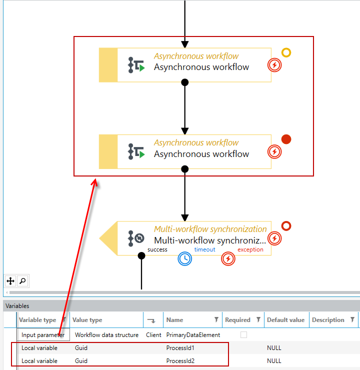
- In this case, 2 Asynchronous workflow activities with the attached workflows have been added to be executed asynchronously.
- Before configuring the synchronization activities, it is necessary to add output mappings in the Asynchronous workflow activities in which the asynchronous workflow instance Id will be passed.
- In the Variables panel, add local variables ProcessId1 and ProcessId2 of type Guid. Two variables are needed because two asynchronous workflows are started.
- Go to Asynchronous workflow and navigate to Output mappings in the Properties panel.
- Define the mapping: drag structure CreatedInstanceId from the source to the Guid field that you added in Variables (ProcessId1).
- Do the same for the second Asynchronous workflow and specify the output mapping for the ProcessId2 field.
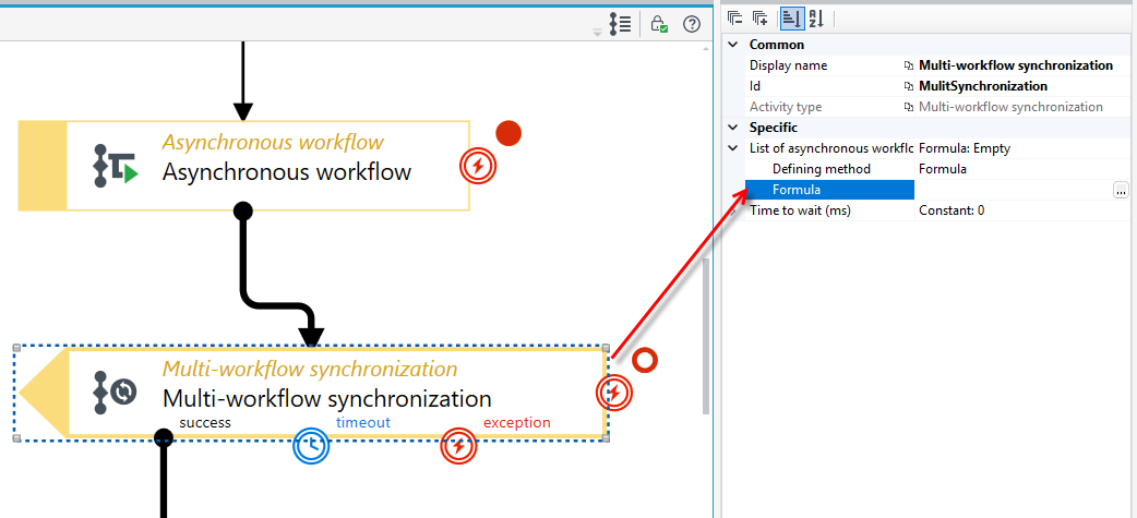
- Now you can set up the Multi-workflow synchronization activity. To specify the list of asynchronous workflow go to the Properties panel and select the button to go to the Formula editor where the workflow list will be passed.
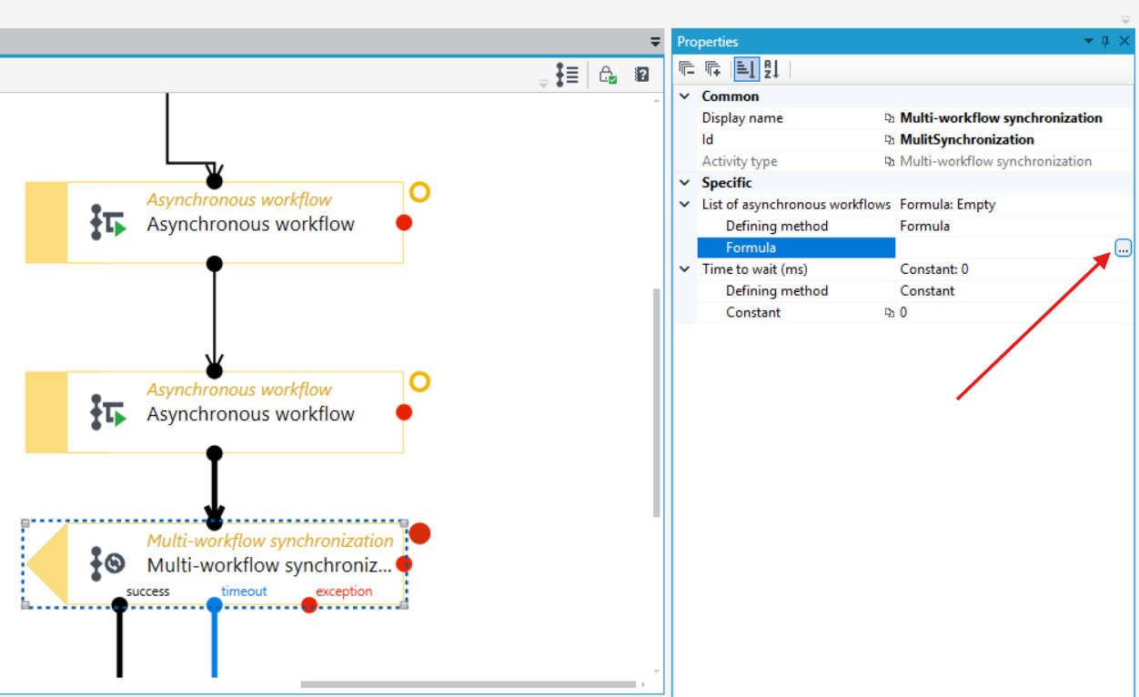
To correctly define a formula with a list of workflows, use the following functions:
- Search for the function Concatenation and drag it to the formula node.
- Next, search for the Identifier into the text function and drag it onto one of the formula arguments.
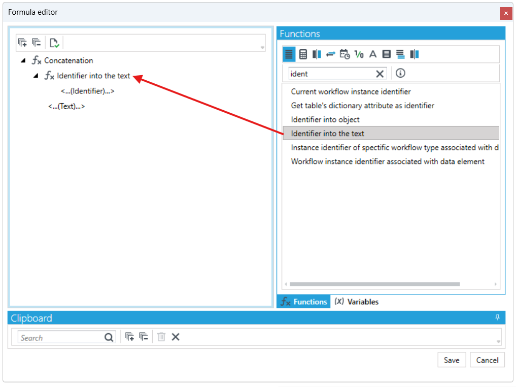
- Go to the Variables > Workflow variables tab and drag the ProcessId1 field to the Identifier field.
- In the second argument of the function, double-click and enter a semicolon.
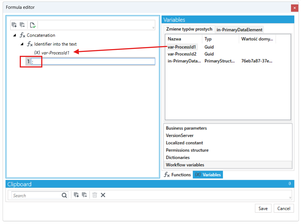
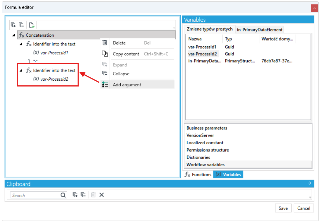
- Right-click the formula node in the Concatenation field and select Add argument.
- On the argument that you added, drag the Identifier into the text function, and then the ProcessId2 field from the workflow variables.
- Save the formula.
The Multi-workflow synchronization activity has 3 output ports which are used in the following situations:
- Correct completion of the workflow’s execution (no errors).
- A timeout before the completion of the workflow’s execution.
- An error in one of the indicated workflows.
Timeout output
- To exit the timeout activity, you can specify the waiting time for the execution of an asynchronous workflow in milliseconds.
- Select the Multi-workflow synchronization activity and go to the Properties panel.
- In the Timeout section, enter a value (value in milliseconds).
The maximum waiting time is 2 minutes, even if you enter a larger value, it will be reduced to 2 minutes. If you want to wait longer, use the loop construct with the State activity in which you can add a time output. Applying the State activity with time output action will put the workflow to sleep and unload it from memory.
Continue workflow
The activity allows you to start another workflow. For the activity, it is necessary to provide the action code to be able to continue the workflow (that is, to define what action code will be transferred to the dormant workflow) and the instance Id of the workflow to be continued.
- Drag an activity from the toolbox and link it to the other activities.
- Go to the Properties panel and in the Action code section, enter the action code defined on the State activity in the workflow that you want to continue. In this case it is Calculate.
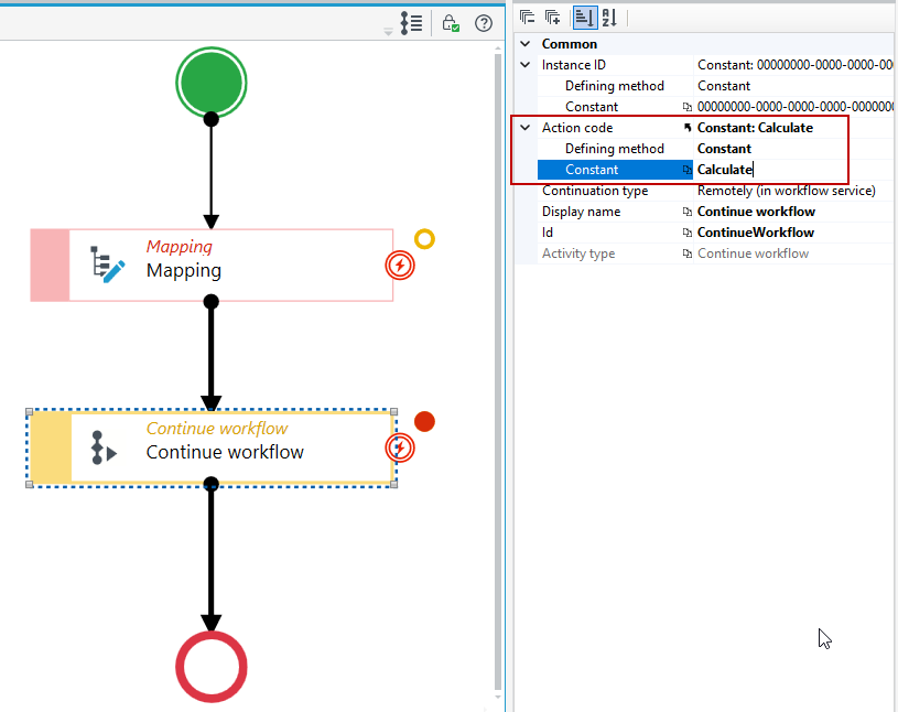
- To select the correct code, go to the workflow you want to continue. Select the State activity, go to the Properties panel and the Output ports section. Enter one of the action codes you have defined in the exit ports.
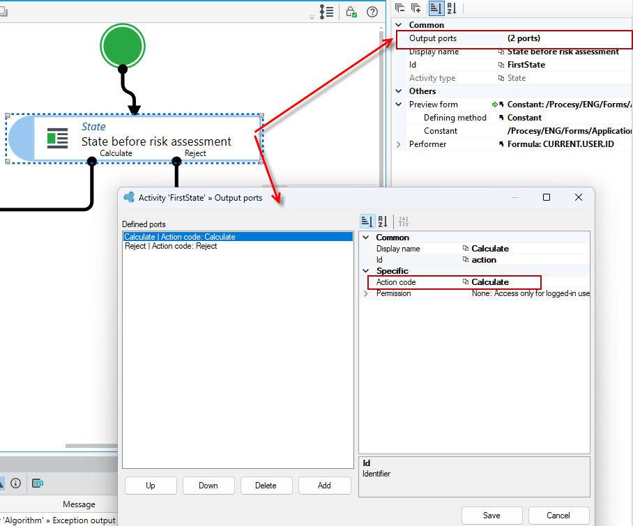
- The next step is to enter the instance Id of the workflow you want to continue. To do this, run this workflow and go to the workflow manager.
- Select the Start Workflow button, and then select Tools and Workflow Manager from the main menu.
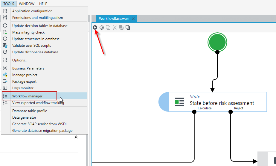
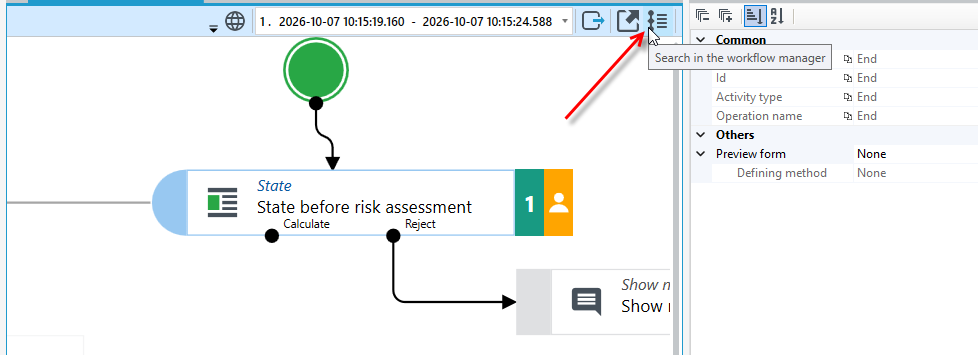
- You can also go to the flow of a running workflow and select the button that takes you to the workflow manager.
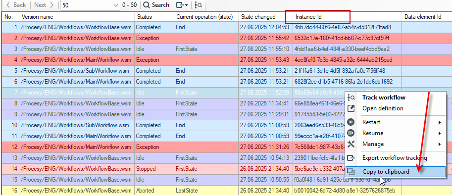
- In the Workflow manager window, find the running workflow and copy the value from the Instance Id column, e.g. by right-clicking the row and selecting Copy to clipboard. The instance Id of the selected workflow is also shown in the Properties panel, in the Activation section.
You can also read the instance Id without opening the workflow manager. The workflow preview opens automatically when you select the Run workflow action, and the Instance Id field is shown in the Properties panel, in the Activation section (see the screenshot in step 6). You can copy it directly from there.
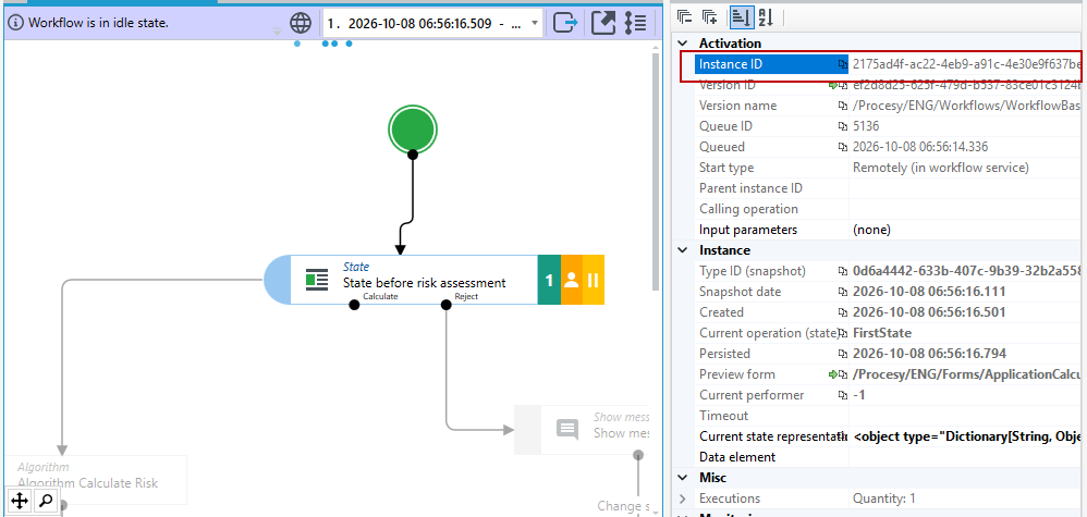
- Go back to the workflow in which you are using the Continue workflow activity, go to the Properties panel and enter the copied instance Id in the Instance Id section.
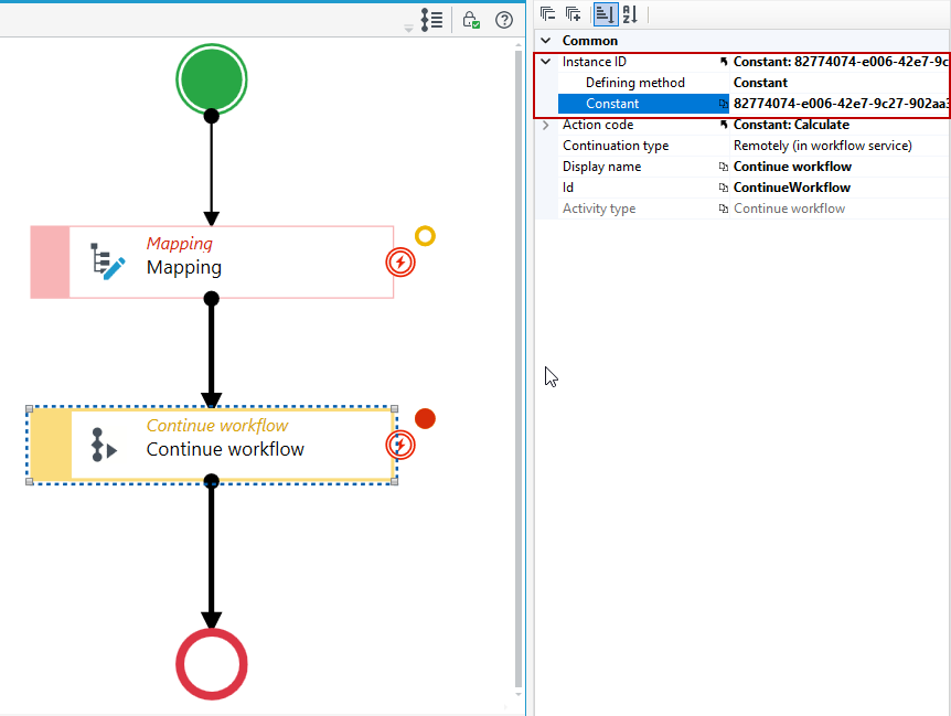
Determining the instance Id with a formula
Instead of entering the copied Id manually, you can determine it with a formula by selecting the workflow directly from the version server:
- Select the Continue workflow activity and go to the Properties panel.
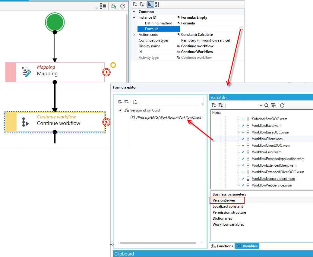
- In the Instance ID section, select Formula in the Defining method field, and then open the formula editor with the
...button in the Formula field. - In the formula editor, go to the Variables tab and then to the VersionServer section.
- Find the workflow you want to continue and drag it onto the formula window.
When you drop the element, the editor automatically adds the Version id on Guid function, which converts the version server element identifier into the Guid value required in the Instance ID field. You don't need to add this function yourself.
Algorithm/Table
The Algorithm activity enables the workflow to invoke the algorithm and the Table activity invokes the decision table. For more information on how to create algorithms and tables, see: Algorithms and Decision Tables.
- Drag an activity from the toolbox and link it to the rest of the activities.
- Go to the activity's Properties panel and select the button in the Table or Algorithm section to load the corresponding algorithm/table.
- Both for the Algorithm and Table activities it is necessary to complete the algorithm date. Both tables and algorithms can have different versions that are valid in particular time intervals, therefore it is important to enter the appropriate date so that the algorithm/table from the valid version at a given time is attached. For more information on table versions, see: Table versioning.
- You can also specify input and output mappings.
- After opening the mapping editor, the target structure window (on the input mappings) shows the data structure that was used in the algorithm, and in the case of a table, the data used to define the table keys. More about algorithms and tables see: Decision Tables, Algorithms.
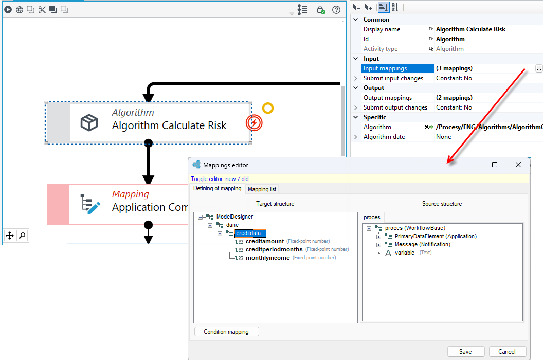
- In the output mappings, the target structure is again the workflow data structure, to which you can pass the values calculated by the algorithm/table.
Web service
The action enables invoking and communicating with external services, including invoking a processing package created in VSoft archITekt Studio and published as a service.
Communication with external services
Calling an external service
If you want to invoke an external service using the Web service activity, drag the activity from the Toolbox to the workspace and configure it correctly in the Properties panel.
WSDL source – it can be the URL of the WSDL, the path to the WSDL file or the WSDL file itself.
Supported Source Types:
- Service address, e.g.
http://test/service.wsdl - File path, e.g.
E:\Myservice.wsdl - Folder path, e.g.
E:\WSDLs\ - Multiple files or folders, such as
E:\MyService.wsdl | E:\MyService.xsd(separated by a new line or|) - Single WSDL - XML describing the service (starting with
<?xml version="1.0" encoding="UTF-8"?>)
The source is used to generate the proxy code while the workflow is designed, and the generated proxy code is compiled when the workflow runs. Refreshing the source regenerates the proxy code and saves it in the workflow definition.
- If you have entered the correct data, i.e. the address or path for the WSDL source, then a proxy code will be generated with the date of generation, in other words, a connection with the service will be established.
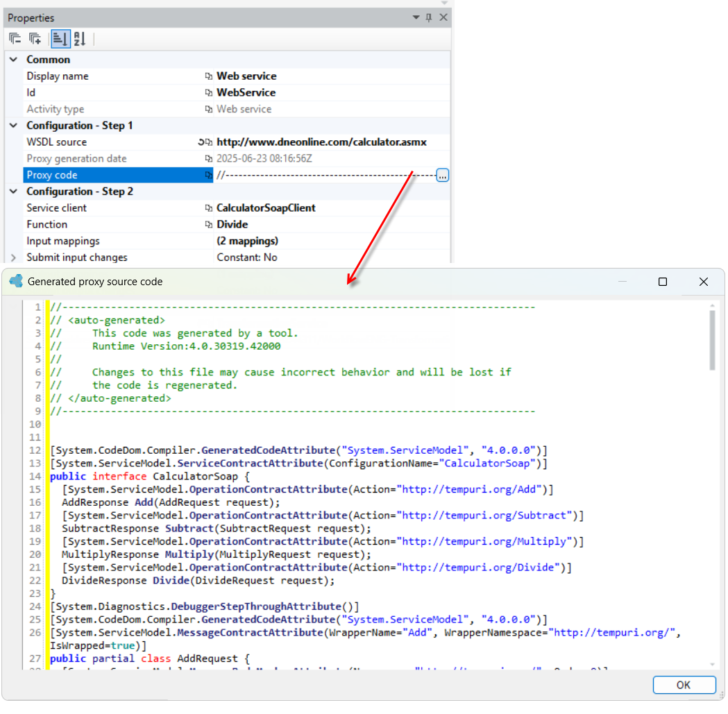
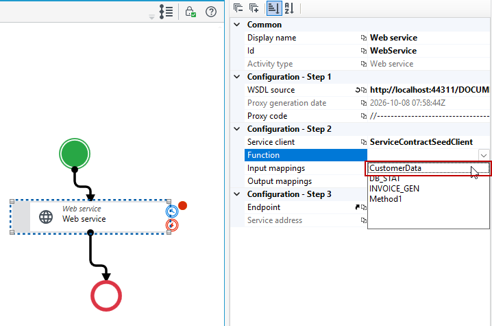
- In the next step, select the method you want to use; the list of available methods will be as offered by the external service.
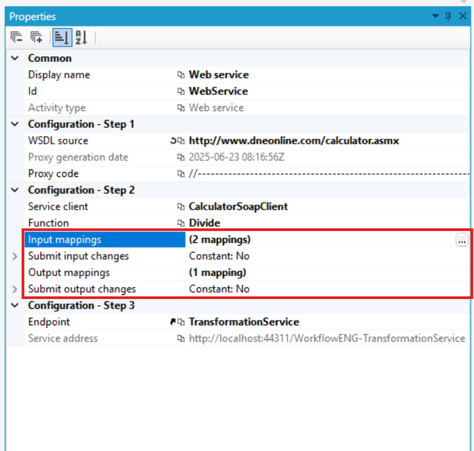
- If needed, specify input and output mappings. If you enter mappings, additional options will be displayed where you can select whether to save the changes on input and output. Selecting the Yes option results in immediate saving of the data to the database after the input and output mappings are performed (without committing the transaction). The option does not delay the save to the next mapping operation, in which you can save the changes, or until the transaction is committed.
If the source has been defined but the methods are still not available, verify that the generated proxy code is correct.
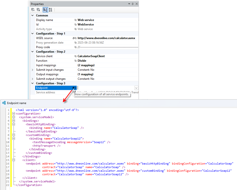
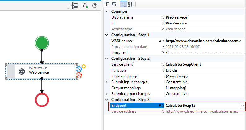
Endpoint – in the Configuration - Step 3 section, select from the list the endpoint through which the service should be called. A service can expose several endpoints (e.g. CalculatorSoap and CalculatorSoap12). For configuration information, see the service documentation. For the call to work, a technical configuration of the endpoints must be added on the archITekt side.
-
Click the Show configuration of all service endpoints icon next to the Endpoint field. A window with the XML configuration of the service opens.
-
Copy the bindings and client sections from the
system.serviceModelnode.
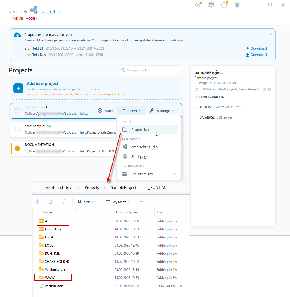
- Go to VSoft archITekt Launcher and open the project files location.
- Create new
Bindings.configandClient.configfiles - paste the contents of the bindings and client sections into them respectively. - Place the created files in the following directories (create any missing directories), so that the paths to the files are as follows:
[PROJECT_FOLDER]\Files\APP\archITekt\Configuration\Environment\Bindings.config.ANY_SUFFIX[PROJECT_FOLDER]\Files\APP\Workflow.Host\Configuration\Environment\Bindings.config.ANY_SUFFIX[PROJECT_FOLDER]\Files\WWW\WWW\Configuration\Environment\Bindings.config.ANY_SUFFIX
In the same way for the Client.config file:
[PROJECT_FOLDER]\Files\APP\archITekt\Configuration\Environment\Client.config.ANY_SUFFIX[PROJECT_FOLDER]\Files\APP\Workflow.Host\Configuration\Environment\Client.config.ANY_SUFFIX[PROJECT_FOLDER]\Files\WWW\WWW\Configuration\Environment\Client.config.ANY_SUFFIX
Configuration introduced using these exact paths will not be lost, for example when upgrading or resetting the project.
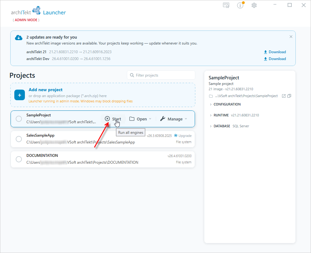
- After defining the configuration, go to VSoft archITekt Launcher and upgrade the project: next to the project, select Manage, then Upgrade in the MAINTENANCE section, and Upgrade project from the submenu. For more information, see: Updating, resetting the project.

- Then start the project services again: next to the project, select Start (Run all engines).
- After performing the above actions, you can select the newly added Endpoint to the service.
Communication with the processing package
You can also use Web service activity to invoke a processing package.
The package you want to invoke must have been saved and published first, and the project services must be restarted in VSoft archITekt Launcher. See: Publishing versions.
Preparing the package:
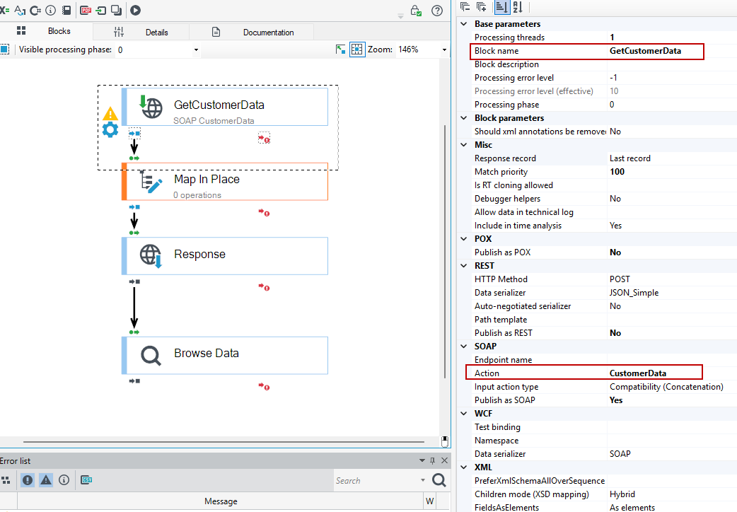
- The package must start with a Request block. To call the package from a workflow, you only need to configure the SOAP section – you don't have to fill in the fields of the WCF section. In the block, in the Properties panel, in the SOAP section, select Yes in the Publish as SOAP field.
- Optionally, enter the operation name in the Action field. The operation will be shown under this name on the Method list of the Web service activity. If you leave the Action field empty, the block name is shown on the Method list. In the example below, the block is called GetCustomerData (Block name field) and the operation CustomerData.
- Save the package and publish it on the version server, see: Publishing versions. Then go to VSoft archITekt Launcher and restart the project services (including TransformationServices.Host) so that the service is available at the service address.
If the environment contains two or more SOAP services whose Request blocks have an input root element with the same name (e.g. the default name Request), the service host may fail to start because of a name conflict. Generating the proxy code in the workflow then fails with the Proxy refresh error window, and the Proxy generation date and Proxy code fields keep the value <no_proxy>. After selecting Show details, a message is displayed saying that the target machine actively refused the connection. For the cause and the solution, see: Root element name conflict.
Configuration of the activity:
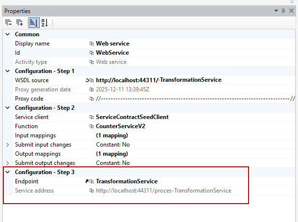
- WSDL source – you will find the service address in the Service address field, after selecting the TransformationService option in the Endpoint field. The address has the form
http://localhost:<port>/<ENVIRONMENT>-TransformationServiceand contains the environment name, so proxy code generated for one environment will not connect to the services of another.
- After generating the proxy code, select the operation you want to call in the Method field. The list contains the operations of all SOAP services published in the environment, under the names from the Action field of the Request blocks (or under the block names if that field is empty). If the Request blocks do not have an endpoint name set, the shared ServiceContractSeedClient client is shown in the Service client field.
- Specify the input mappings (e.g. the CustomerId field from a workflow variable) and the output mappings (e.g. the Name, TaxId and Address fields to workflow variables).
For more information on building a SOAP service package, see: SOAP service called from a workflow.
Refreshing data in a Workflow after using the Web service activity
If you use the Web service activity in a workflow and then want to continue working in the workflow on the same data that has been modified by the service (or if the processing package has made modifications to the data as part of the Web service activity), it is necessary to refresh the data in the workflow.
For example, if you are working on a given data object in the workflow and then send this data to a package via the Web service activity, where the package performs modifications and the data is returned to the workflow, then in order for the workflow to read the changed data, you need to refresh it.
You can refresh data in two ways:
- by using the Refresh data element activity in the workflow – see: Refresh data element,
- by extending the workflow with the refresh option using an additional state with a timeout output and a JavaScript action on the form. The scenario for this use case is described below.
In the following case, a workflow is launched on the form, which sequentially calls a processing package via the Web service action, which modifies the data.
In order to refresh the data in the workflow, add a State activity with a timeout output. To obtain an immediate time output, you can use formulas, specifically the UtcNow function.
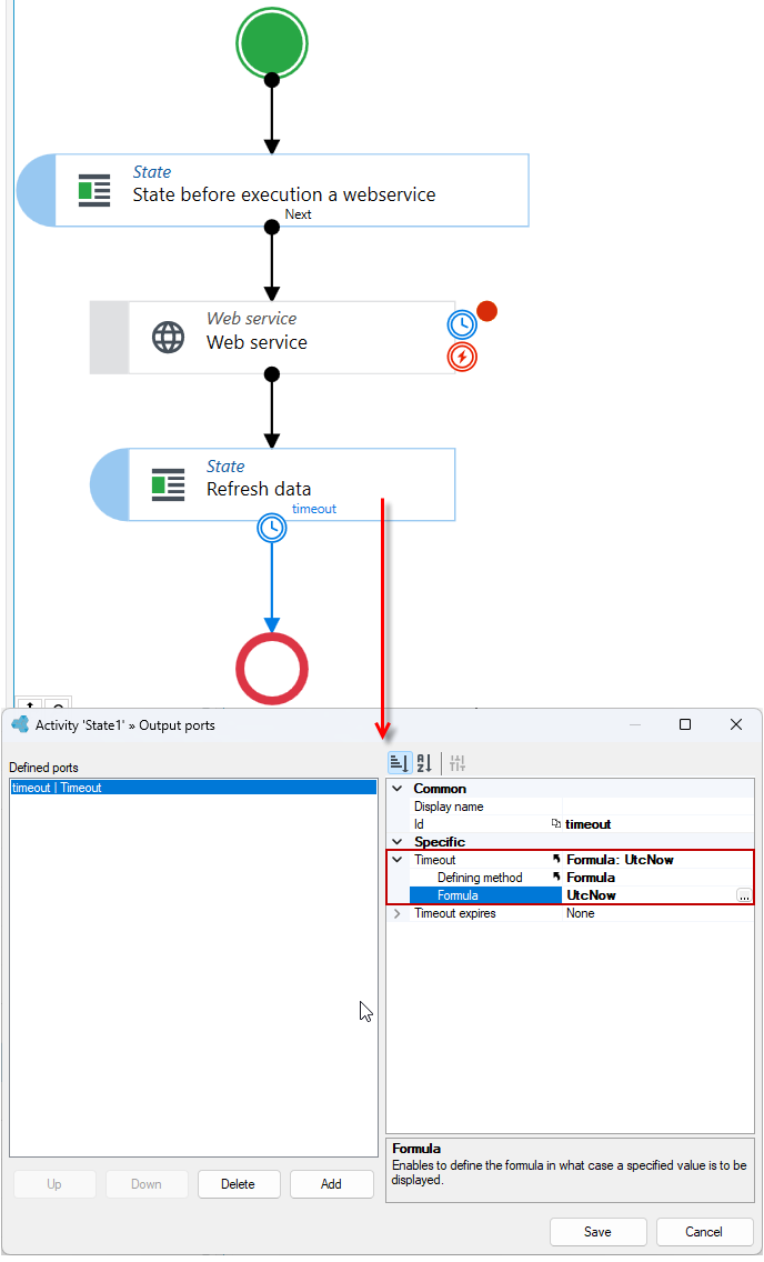
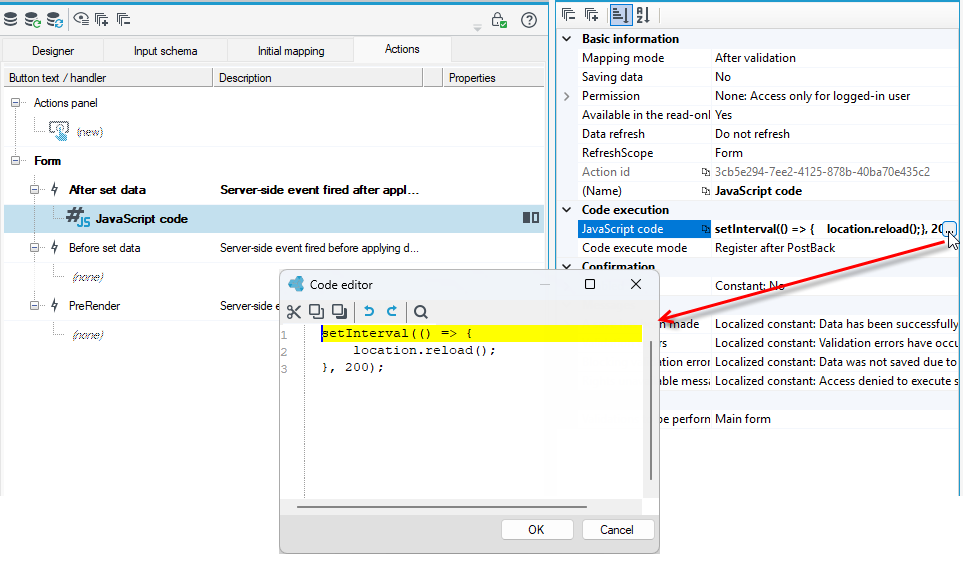
Unfortunately, the time output in the workflow does not refresh the forms in the web application. To do this, you can, for example, use JavaScript code on a technical form or a form that is linked to the workflow preview to refresh the page at a certain interval (e.g., 200 ms). This will refresh the form until it transitions to the next state.
setInterval(() => {
        location.reload();
    }, 200);
Show message
The action displays a message that you can configure yourself. The message will be displayed on the closest status form.
The message will only be displayed if a particular part of the workflow runs synchronously within the workflow path of a user-operated web application. In the case of background workflows (asynchronous, resumed from a timed output or resumed by external services) the message will be intercepted and sent to the application logs.
- Drag an activity from the toolbox and link it to the other activities.
- Go to the Properties panel and enter data in the Display text fields and select the message type.
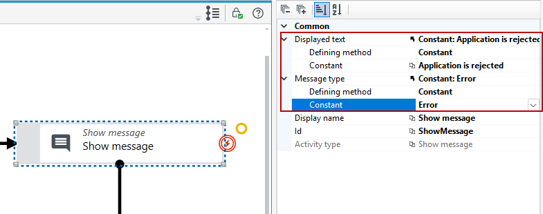
In this case, the message will be displayed after the performed action on the form (after the data is rejected).
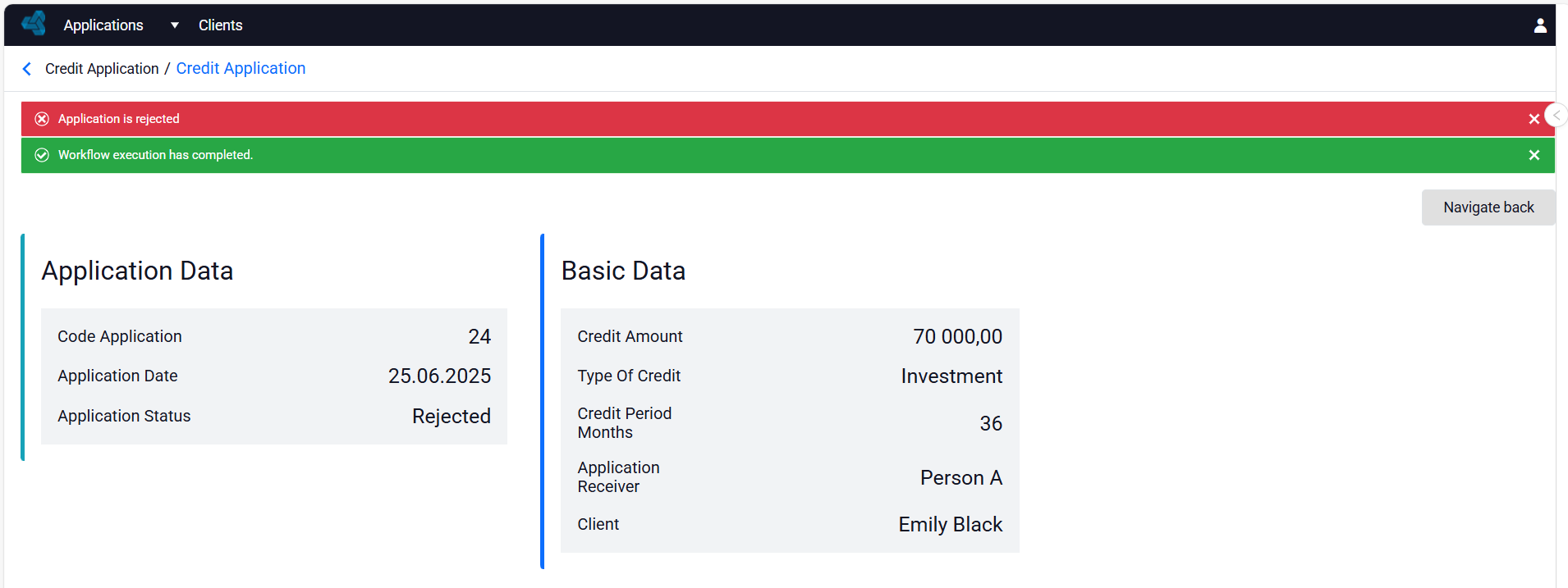
The message type affects the formatting of the displayed text.
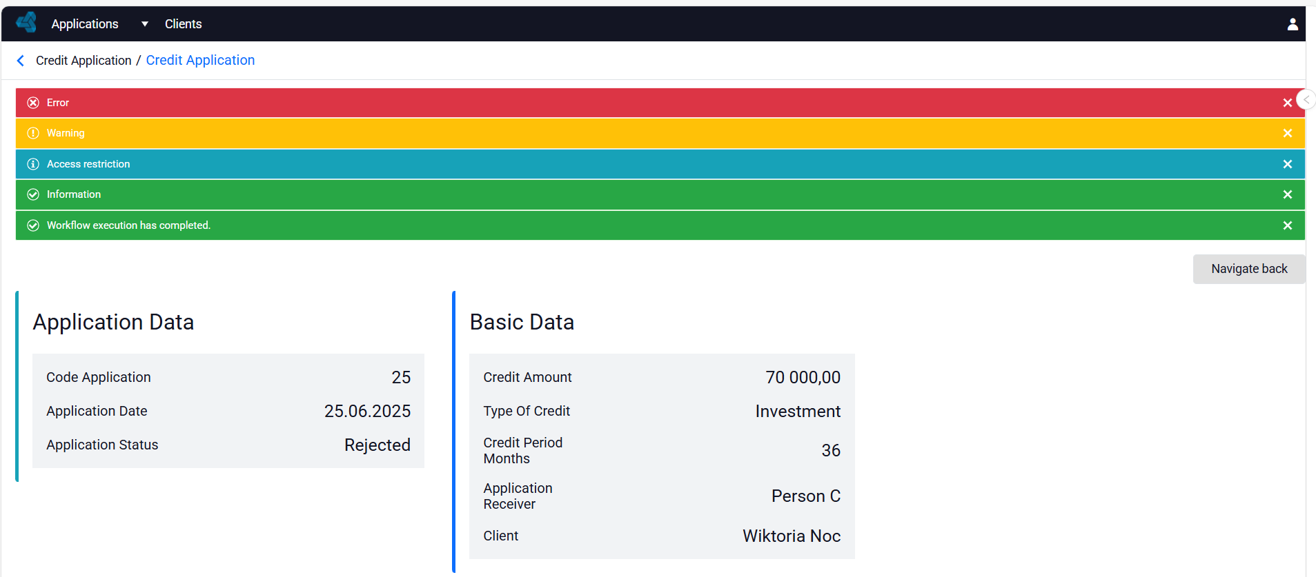
If, in the process definition, there are no further states (forms) for the process to transition to after the message is displayed, the message will be displayed on the process preview form, if one has been configured. See: Preview form.
See how to call a workflow from a form action
Calling a workflow from a form
Refresh data element
This operation allows you to refresh a data element for a selected variable or data structure. It is particularly useful when a synchronized asynchronous subprocess that operates on the same data is called within a process, or when a package is executed that modifies the same data record or uses an external service.
For example, if you are working on a given data object in a workflow and then send this data to a package via the Web service action, where the package performs modifications and the data is returned to the workflow, then in order for the workflow to read the changed data, you need to refresh it.
You can do this in two ways:
- by using refresh on an additional state with a timeout in the workflow and a form with JavaScript code - see: Refreshing data in a Workflow after using the Web service activity.
- by using the Refresh data element activity.
In the following case, a subworkflow called by the Asynchronous workflow activity performs mappings on a given data element (changes the status of the request). In order for the data changed by the subworkflow to be refreshed in the main workflow, add the Refresh data element activity. For example, if you want to display the changed status to the user on the form or through the Show message activity.
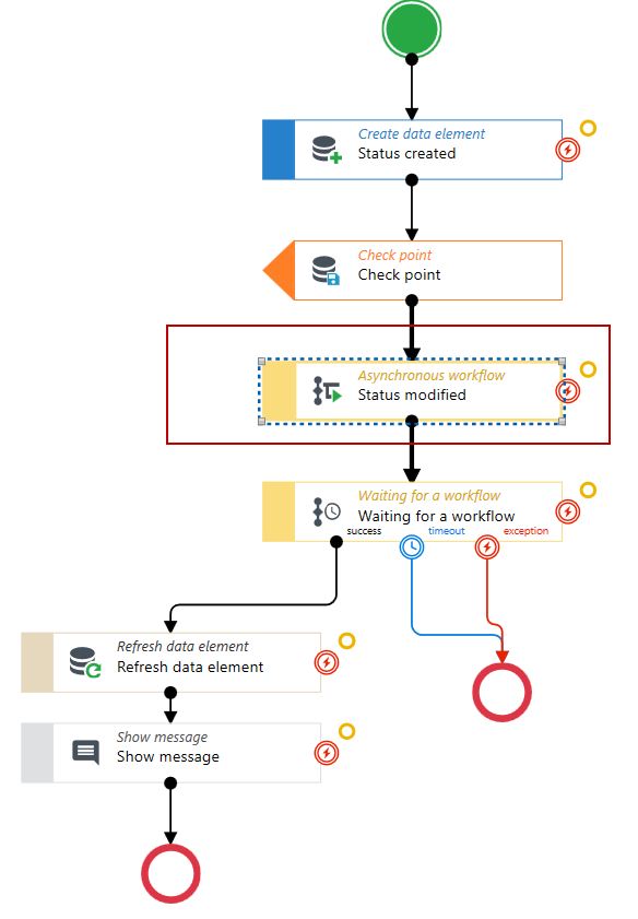
Configuring the activity:
- Drag the Refresh data element activity from the toolbox and place it where the workflow should read the current data – in the example above, on the success output of the Waiting for a workflow activity, i.e. after the subworkflow has finished.
- Select the activity and, in the Properties panel, in the Specific section, select the variable whose data should be refreshed from the list in the Variable name field, e.g. in-PrimaryDataElement.
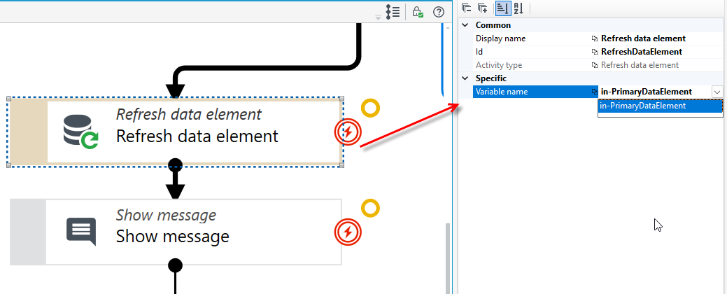
The Variable name field must be filled in. Without a variable, the activity does not know which data element to refresh.
Throw error
The Throw error activity is used to deliberately end a workflow path with an error. It corresponds to the error end event in BPMN notation.
The activity lets you define a custom error message. It replaces the previous workarounds based on deliberately generating an error in a Mapping activity.
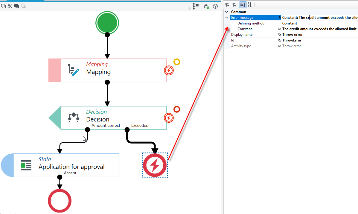
- Drag the Throw error activity from the toolbox and connect it to the activity after which the error should be raised. The activity is shown on the diagram as a red circle with a lightning symbol and ends the given workflow path – it is not connected to an End element.
- Select the activity and, in the Properties panel, expand the Error message section. In the Defining method field, choose whether the message is a constant text (Constant) or is determined by a formula (Formula). Then enter the message text in the Constant field or define the formula in the Formula field.
In the example below, the Decision activity checks whether the credit amount is within the limit. If it is, the workflow follows the Amount correct output to the Application for approval state. Otherwise, the workflow follows the Exceeded output to the Throw error activity with the message "The credit amount exceeds the allowed limit".
The activity also supports subworkflow scenarios. If an error is thrown in a subworkflow, it is passed on to the parent workflow, where it can be handled using the error handling output port of the activity that calls the subworkflow. See: Output port for error handling.
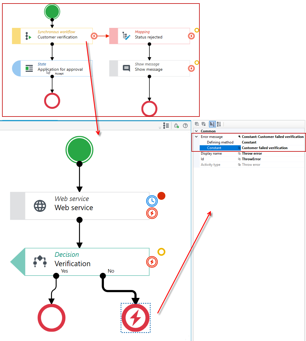
In the example below, the main workflow calls the Customer verification subworkflow using the Synchronous workflow activity. In the subworkflow, the Web service activity checks the customer, and the Decision activity directs the flow:
- if the customer has been verified (Yes output), the subworkflow ends normally and the main workflow goes to the Application for approval state,
- if not (No output), the Throw error activity raises an error with the message "Customer failed verification". The error is passed to the main workflow, which follows the error port of the Synchronous workflow activity – it sets the application status to rejected (Mapping activity) and informs the user (Show message activity).
Output port for error handling
For some activities, an additional output port is defined by default, which you can use to configure alternative workflow execution path in case of an error in a given activity.
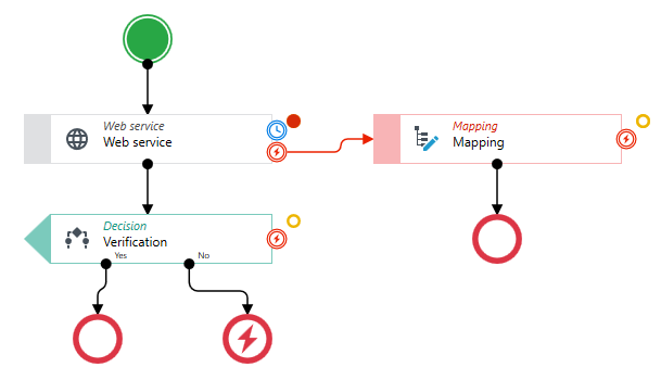
The output port is marked with a BPMN-compliant error symbol to the right of the item representing the activity. The symbol is highlighted when you hover over it. The port is available for the activities:
- Mapping
- Decision
- Create a data element
- Web service
- Algorithm
- Table
- Show message
- Asynchronous workflow
- Synchronous workflow
- Multi-asynchronous workflows
- Continue workflow
In the following case, if the workflow reaches the Web service activity and fails to connect to the service and the action fails, the workflow will follow the path that was defined for the activity when it encountered an error.
The activities Waiting for a workflow and Multi-workflow synchronization also have default output ports for error handling. However, in this case, the error-out port must be linked to the next element of the workflow. It can be a separate path in the workflow for handling the error, or you can link the output port to the same item as if the workflow was properly executed. The additional error handling port can be handled in the same way as for the other activities.
In the example below, both activities have all three outputs connected: success (correct execution), timeout (marked with a clock icon) and exception (marked with the BPMN error symbol). The timeout and exception outputs can lead to separate handling paths or to the same activity.

Useful workflows formulas
The formula editor allows you to use workflow formulas that are useful when designing workflows.
- Go to the mapping editor and then to the formula editor.
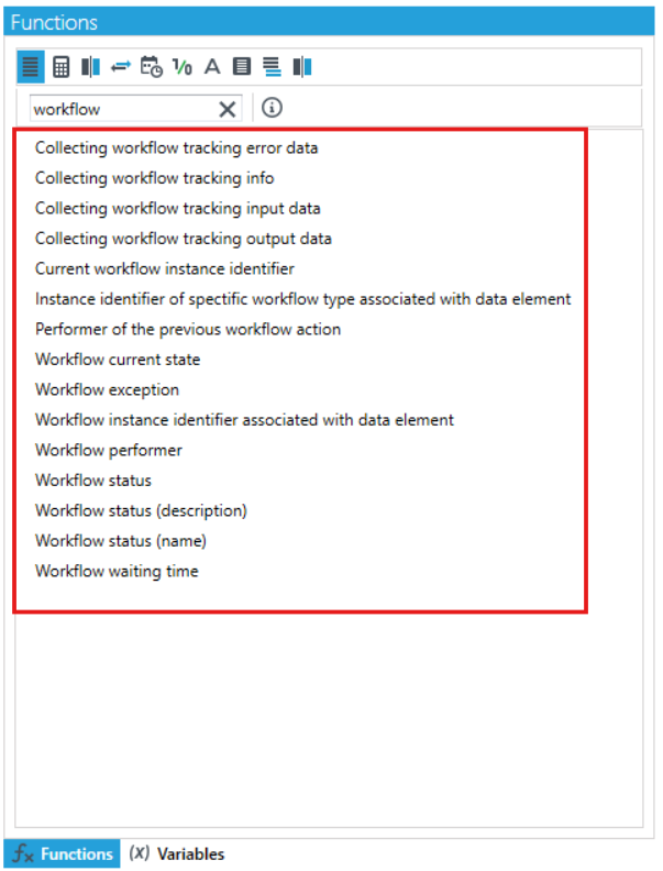
- You can search for formulas in the list.
Useful formulas:
- to retrieve the instance Id based on data - useful especially in the context of activating workflows,
- to get the status, date/time of next continuation, last exception, to get the instance Id of the current workflow - informative formulas.
If you want to get the instance Id of the workflow you want to continue, you can apply a formula. In this case, select the Instance Id of the workflow running on the data formula.
You can find more information about the formula editor here: Formulas.